Ion beam irradiation apparatus for suppressing charge up of substrate and method for the same

a technology substrate, which is applied in the field of ion beam irradiation apparatus, can solve the problems of unsatisfactory conventional techniques for satisfying such requirements, unsatisfactory approaches to merely reducing radio frequency electric power b>18/b>, and high negative charge-up voltage of the substrate surface, so as to achieve easy and reliable generation, reduce electron energy in the plasma, and easy and reliable generation

Inactive Publication Date: 2006-08-08
NISSIN ION EQUIP CO LTD
View PDF11 Cites 10 Cited by
  • Summary
  • Abstract
  • Description
  • Claims
  • Application Information

AI Technical Summary

Benefits of technology

[0028]It is an object of the present invention to provide an ion beam irradiation apparatus which is capable of reducing electron energy in a plasma stream generated by a plasma generator of a radio frequency discharge type, while generating plasma, and hence of reducing a charge-up voltage of a substrate.
[0035]From this fact, the inventor of the present invention found the fact that the electron energy in the plasma can be reduced while maintaining the generation of the plasma when the amplitude of the radio frequency electric power supplied to the plasma generator is controlled such that a high relative power state and a low relative power state (e.g., its value near 0) are alternately repeated at fixed periods. The reduction of the electron energy leads to reduction of the charge voltage of the substrate.
[0038]Even in the modulation wave mode, the plasma can be generated in the plasma chamber. However, in the continuous wave mode, the plasma is more easily and reliably generated in the plasma chamber since in this mode, no plasma-density reduction period is present.
[0039]Thus, if a selecting device for selecting the mode of the radio frequency electric power 18 output from the radio frequency electric source 16a is employed, the plasma is more easily and reliably generated in the plasma chamber.
[0040]After the plasma is generated, the electron energy in the plasma is reduced while generating the plasma. Accordingly, the ion beam irradiation apparatus produces the advantages comparable with those by the first ion beam irradiation apparatus.

Problems solved by technology

The conventional technique is still unsatisfactory for satisfying such a requirement.
As a result, the negative charge-up voltage of the substrate surface is likely to be high.
The approach of merely reducing the radio frequency electric power 18 is unsatisfactory for effective suppression of the charge of the substrate 4.

Method used


Image

  • Ion beam irradiation apparatus for suppressing charge up of substrate and method for the same
  • Ion beam irradiation apparatus for suppressing charge up of substrate and method for the same
  • Ion beam irradiation apparatus for suppressing charge up of substrate and method for the same

Examples


Embodiment Construction

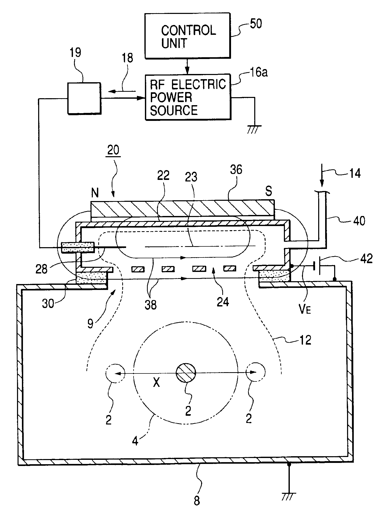
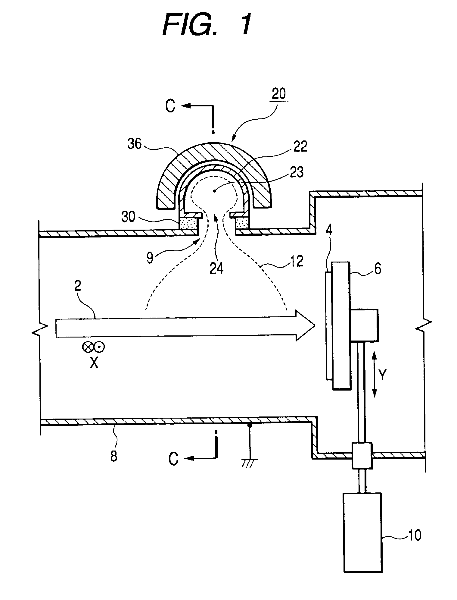
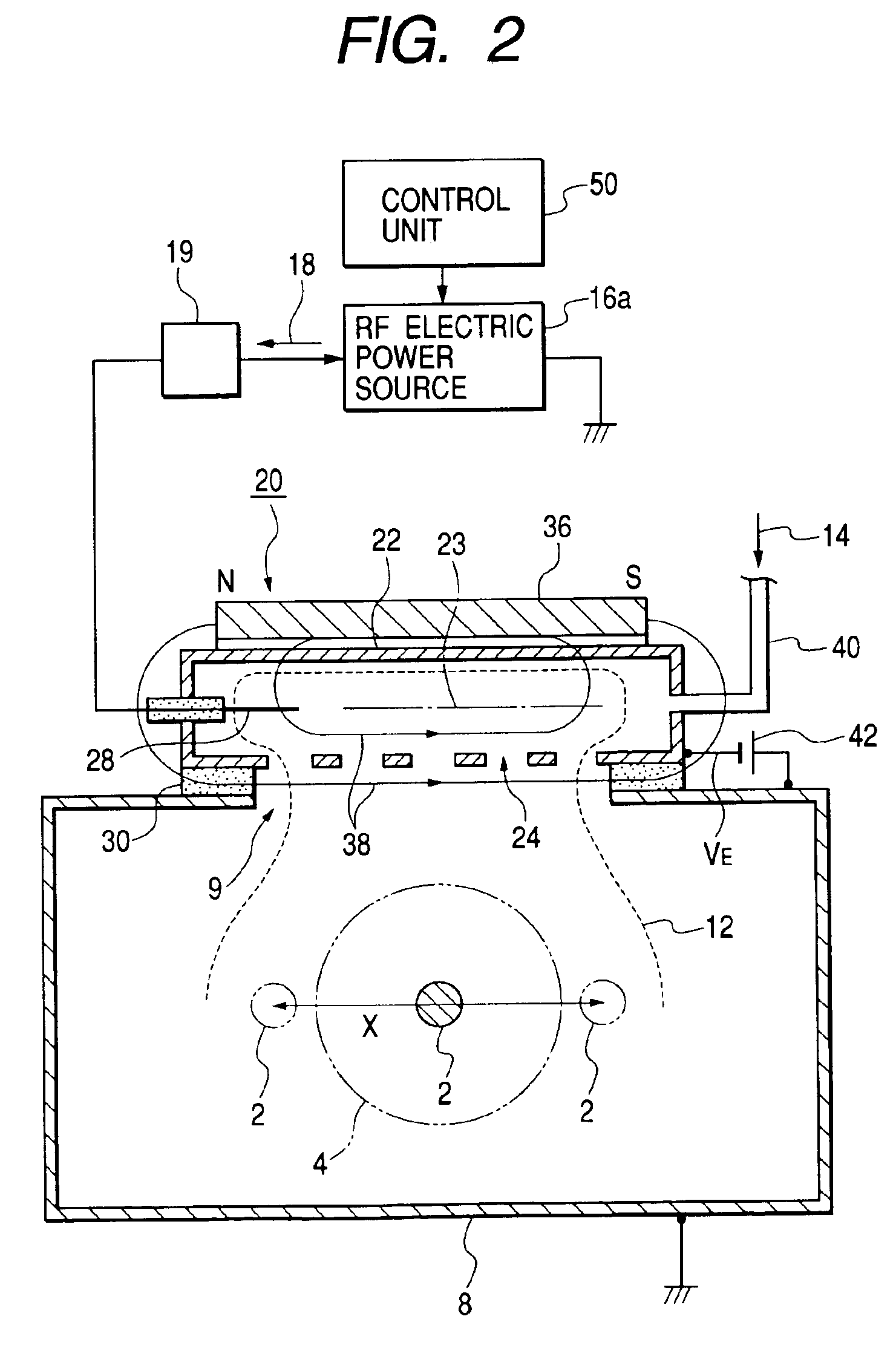
[0050]FIG. 1 is a side view showing an ion beam irradiation apparatus of the present invention. FIG. 2 is a cross sectional view taken on line C—C in FIG. 1. In those figures, like or equivalent portions are designated by like reference numerals in FIG. 9 showing the related art. A description will be given placing emphasis on different portions from those in the related art.

[0051]A structure of the plasma generator 20 will first be described. In this instance, a plasma generating vessel 22 takes a cylindrical shape elongated in an axis 23, which extends in scan directions X of an ion beam 2. A gas introducing pipe 40 for introducing a gas 14 into the plasma generator and antenna 28 are mounted on both ends of the plasma generating vessel 22. Plasma emission holes 24 are laid along the axis 23. With such a structure, a plasma 12 is generated in the plasma generating vessel 22. The plasma 12 takes a shape, which is long in the scan directions X and large in width. Such a wide plasma ...


PUM

PropertyMeasurementUnit
frequencyaaaaaaaaaa
frequencyaaaaaaaaaa
frequencyaaaaaaaaaa

Abstract

An ion beam irradiation apparatus is equipped with a plasma generator which generates a plasma and supplies it to a region in the vicinity of the upstream side of a substrate, thereby suppressing a charging up of a surface of the substrate, which results from an irradiation of the ion beam. The radio frequency electric source for supplying the plasma for generating the plasma to a plasma generator is a radio frequency electric source for producing a radio frequency electric power formed by amplitude modulating an original radio frequency signal.

Description

BACKGROUND OF THE INVENTION[0001]1. Field of the Invention[0002]An present invention relates to an ion beam irradiation apparatus for implanting ions into a substrate by irradiating the substrate with an ion beam, more particularly relates to improvement for suppressing a charging (charge-up) of the substrate when it is irradiated with the ion beam.[0003]2. Description of the Related Art[0004]There is a proposal of suppressing a charge-up of a substrate when it is irradiated with ion beam. Plasma generated from a plasma generator is supplied to a region near the substrate. Electrons included in the plasma are used for neutralizing a positive charge generated by the ion beam irradiation. The proposed technique supplies electrons of lower energy to the substrate, when comparing with the technique utilizing secondary electrons emitted from an object when it is irradiated with electrons emitted from the filament. Accordingly, the proposed technique has an advantage of reducing the negat...

Claims


Application Information

Patent Timeline
Patent Type & Authority Patents(United States)
IPC IPC(8): H01J37/08H05H1/46C23C14/48H01J37/02H01J37/077H01J37/317H01L21/265
CPCC23C14/48H01J37/32082H01J37/026H01J2237/31701H01L21/265
Inventor HAMAMOTO, NARIAKI
Owner NISSIN ION EQUIP CO LTD
Why Eureka
Try Eureka