
Lithographic actuator mechanism, lithographic apparatus, and device manufacturing method

a technology of actuator mechanism and actuator body, which is applied in the direction of dynamo-electric machines, printers, instruments, etc., can solve the problems of degrading thermal performance, limited efficiency of lorentz actuator, and limited dynamic performance, so as to reduce uneven temperature distribution, reduce damping and heating, and increase the resistance of eddy current paths

Active Publication Date: 2006-08-08
ASML NETHERLANDS BV
View PDF14 Cites 2 Cited by
  • Summary
  • Abstract
  • Description
  • Claims
  • Application Information

AI Technical Summary

Benefits of technology

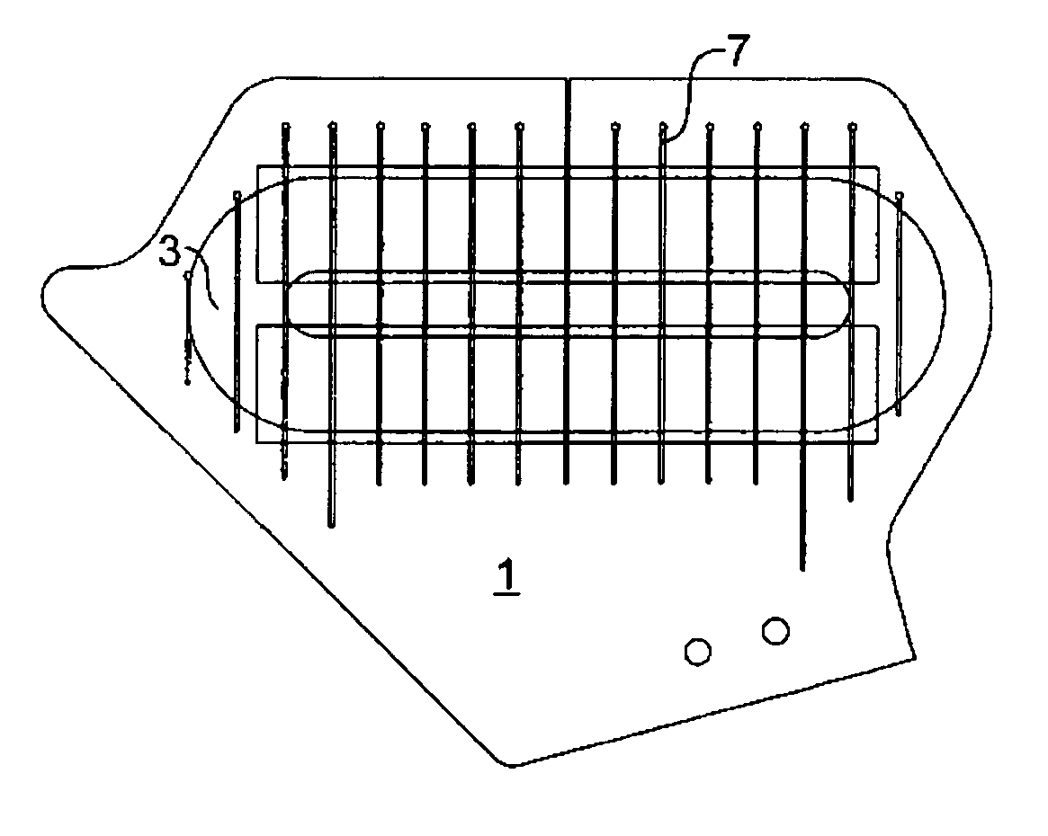
[0020]The slits in the cooling element thus provided act as barriers for the circulating eddy currents, obliging them to take paths of higher electrical resistance. This has the effect of reducing the size of the eddy currents, thus reducing damping forces and the levels of dissipative heating.
[0026]The above embodiments describe improvements to the Lorentz actuator that result in improved damping behavior, reduced hotspot temperatures and overall radiation levels to surrounding heat sensitive components such as the mirror block, and reduced actuator mass and volume since the more effective cooling allows for increased current densities.

Problems solved by technology

However, during operation, the efficiency of the Lorentz actuator is limited by eddy currents induced in the body of the cooling plates by time-varying external magnetic fields.
Damping forces arising from the generation of eddy currents degrades the dynamical performance of the actuator and the associated dissipative heating degrades the thermal performance.
Materials with lower electrical conductivity but acceptable thermal conductivity, such as ceramics, suffer less from eddy current heating than metals but machining of the cooling channels in these materials tends to introduce micro-cracks and imperfections that reduce machine reliability by increasing the risk of coolant leakage and mechanical failure.
In these types of systems, the conventional configurations of cooling plates are not sufficient to adequately control the temperature of the coils.

Method used


Image

  • Lithographic actuator mechanism, lithographic apparatus, and device manufacturing method
  • Lithographic actuator mechanism, lithographic apparatus, and device manufacturing method
  • Lithographic actuator mechanism, lithographic apparatus, and device manufacturing method

Examples


embodiments

[0053]As noted above, lithographic apparatus employ actuating mechanisms for positioning a part or component of the apparatus. Such actuators are applied for positioning a substrate table, a part of an irradiation system, a part of an illumination system or any other part of the lithographic apparatus.

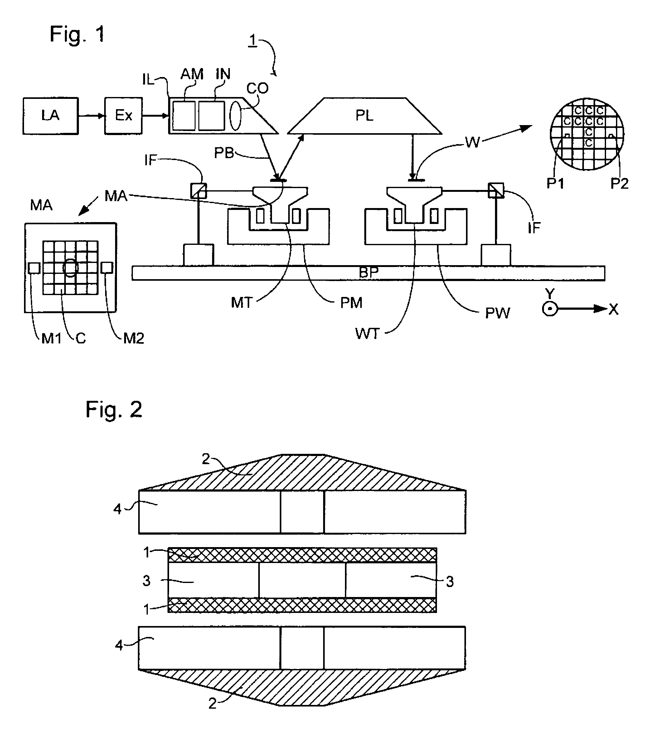
[0054]Generally, a Lorentz actuator comprises a magnet assembly and an electrically conductive element, such as a coil arrangement. FIG. 2 depicts a side view of the magnetic assembly for a Lorentz actuator. In a typical application, the coil unit, which consists of a coil 3 and cooling elements 1 is connected to the long stroke of the substrate or mask stage (WT or MT), while the magnets 4 with back irons 2 are connected to the short stroke of the mirror block, on which the substrate W or mask MA is mounted.

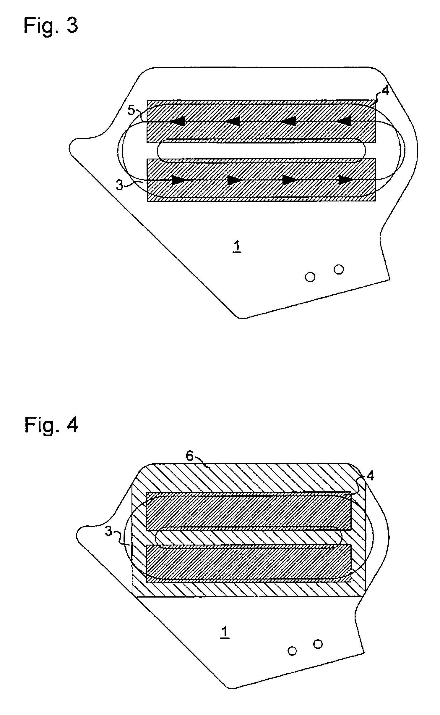
[0055]In operation, changing magnetic fields linked by the conductive material of the cooling elements 1 cause eddy currents 5 to flow in the cooling elements 1. The sense of these...


PUM

PropertyMeasurementUnit
wavelengthaaaaaaaaaa

Abstract

Lorentz actuators generate heat due to electrical dissipation in the field coils. As the field through the coils changes, eddy currents are induced in cooling elements leading to undesirable damping forces and heating. The present invention provides an improved design that reduces eddy currents by incorporating slits in the cooling element. Slits are preferably perpendicular to the induced electric field and parallel to each other, and reduce the magnitude of the eddy currents by forcing them to take paths of higher electrical resistance.

Description

BACKGROUND OF THE INVENTION[0001]Priority Information[0002]This application claims priority from European Patent Application No. 03251446.5, filed Mar. 11, 2003, herein incorporated by reference in its entirety.[0003]1. Field of the Invention[0004]The present invention relates to a lithographic apparatus, and in particular, to a lithographic actuator mechanism and an associated device manufacturing method.[0005]2. Description of the Related Art[0006]Lithographic apparatus can be used, for example, in the manufacture of integrated circuits (ICs). In such a case, a patterning device may be used to generate a desired circuit pattern corresponding to an individual layer of the IC, and this pattern can be imaged onto a target portion (e.g. comprising one or more dies) on a substrate (silicon wafer) that has been coated with a layer of radiation-sensitive material (resist).[0007]The term “patterning device” as here employed should be broadly interpreted as referring to a device that can b...

Claims


Application Information

Patent Timeline
Patent Type & Authority Patents(United States)
IPC IPC(8): G03B27/42G03B27/58G03B27/62H01L21/027G03F7/20H02K9/22H02K41/02H02K41/03H02K41/035
CPCG03F7/70758H02K41/0356H02K9/22G03F7/70858H02K9/227G03F7/20
Inventor HOL, SVEN ANTOIN JOHANBUIS, EDWIN JOHANVAN DER SCHOOT, HARMEN KLAASVREUGDEWATER, PATRICIA
Owner ASML NETHERLANDS BV
Learn More