Polarization maintaining dispersion controlled fiber laser source of ultrashort pulses

a fiber laser and ultrashort pulse technology, applied in the direction of laser details, active medium shape and construction, optical resonator shape and construction, etc., can solve the problems of limiting the early saturable absorber design, weak intraband contribution, and reducing the bandwidth

Inactive Publication Date: 2006-08-08
IMRA AMERICA
View PDF86 Cites 97 Cited by
  • Summary
  • Abstract
  • Description
  • Claims
  • Application Information

AI Technical Summary

Benefits of technology

[0021]The present invention is directed to a mass-producible passively modelocked fiber laser. By incorporating apodized fiber Bragg gratings, integrated fiber polarizers and concatenated sections of polarization-maintaining and non-polarization-maintaining fibers, a fiber pig-tailed, linearly polarized output can be readily obtained from the laser. By further matching the dispersion value of the fiber Bragg grating to the inverse, or negative, of the dispersion of the intra-cavity fiber, the generation of optimally short pulses with a large optical bandwidth can be induced. In this regard, either positive dispersion fiber in conjunction with negative dispersion fiber gratings or negative dispersion fiber in conjunction with positive dispersion fiber gratings can be implemented. Preferably, the dispersion characteristics of the fiber Bragg grating and the dispersion characteristics of the rest of the intra-cavity elements are matched to within a factor of three. Even more preferably, these characteristics are matched within a factor of two, or within a factor in the range of 1.0 to 2.0. Also preferably, the Bragg grating has a chirp rate greater than 80 nm / cm. More preferably, the Bragg grating has a chirp rate greater than 160 nm / cm. Most preferably, the Bragg grating has a chirp rater greater than 300 nm / cm. To maximize the output power and the pulse repetition rate, the use of wide-bandwidth fiber Bragg gratings with low absolute dispersion is preferable. These fiber Bragg gratings are also used as end-mirrors for the cavity and allow the transmission of pump light to the intra-cavity gain fiber. The fiber Bragg gratings are conveniently produced using phase masks.
[0022]Alternatively, fiber couplers can be used inside the fiber cavity. Generally, sections of polarization-maintaining and non-polarization-maintaining fiber can be concatenated inside the fiber cavity. The non-polarization-maintaining section should then be short enough so as not to excessively perturb the polarization state. Intra-cavity sections of non-polarization-maintaining fiber preferably comprise all-fiber polarizers to lead to preferential oscillation of one linear polarization state inside the cavity. Similarly, when directly concatenating polarization-maintaining fiber sections, the length of the individual section should be long enough to prevent coherent interactions of pulses propagating along the two polarization axes of the polarization-maintaining fibers, thereby ensuring a maximum in pulse stability.
[0025]In aluminum containing semiconductors the surface area can induce a low optical damage threshold triggered by oxidization of the surface. In order to prevent optical damage of aluminum containing surface areas a passivation layer, e.g., InP, InGaAs or GaAs, is incorporated. SA degradation is further minimized by optimizing the optical beam diameter that impinges on the SAM. In one implementation the SAM and an intra-cavity fiber end can be either butt-coupled or brought into close contact to induce modelocking. Here, the incorporation of a precision AR-coating on the intra-cavity fiber end minimizes any bandwidth restrictions from etalon formation between the SAM and the fiber end. Etalons can also be minimized by appropriate wedging of the fiber ends. The beam diameter inside the SAM can be adjusted by implementing fiber ends with thermally expanded cores. Alternatively, focusing lenses can be directly fused to the fiber end. Moreover, graded-index lenses can be used for optimization of the focal size and working distance between the fiber tip and SA surface.
[0027]The use of bi-or multi-temporal saturable absorbers allows the design of dispersion compensated fiber laser operating in a single-polarization state, producing pulses at the bandwidth limit of the fiber gain medium. Additional spectral broadening can be obtained by launching these pulses into highly nonlinear fibers, allowing for the generation of broad-bandwidth pulses with bandwidths exceeding one octave for use in optical coherence tomography or in precision metrology.

Problems solved by technology

However, these early saturable absorber designs were restricted in that they contained nonlinear layers with a spacing of exactly an integer multiple of a predetermined optical period.
Such thin semiconductor layers generally restrict the bandwidth over which pulse shaping is possible with saturable absorbers.
However, when the carriers are photo-excited at the band edge, the intraband contribution becomes weak due to the low carrier temperature.
In this case, the nonlinear optical response is governed by the interband dynamics including trap center assisted recombination and carrier relaxation with two different time constants cannot necessarily be observed and moreover, the ratio of carrier centers relaxing at the two different time constants cannot be controlled.
However, to date no control of the ratio of carriers relaxing at these time constants was possible.
Although these early modelocked fiber lasers could further accommodate devices that enabled wavelength tuning, a fiber pig-tailed output signal with a well-defined polarization state was not easily attainable.
A limitation with such designs is the required precision-polishing and AR-coating at the back-end of the saturable absorber to avoid the formation of satellite pulses inside the cavity.
This design has limited functionality due to the presence of at least two long lengths of fiber with different dispersion coefficients for dispersion compensation, as well as the presence of non-polarization maintaining fiber, greatly complicating polarization control inside the cavity.
The designs described in Pat. Nos. '741 and '867 lack appropriate all-fiber, high polarization extinction, polarizing elements that are generally required to minimize the formation of satellite pulses at the fiber output.
Moreover, these patents do not describe all-fiber means to control the spot size on the intra-cavity saturable absorber; control of the spot size is required to optimize the life-time of the saturable absorber.
Equally none of the prior art describes ion-implanted saturable absorber designs with controlled ion depth penetration.

Method used


Image

  • Polarization maintaining dispersion controlled fiber laser source of ultrashort pulses
  • Polarization maintaining dispersion controlled fiber laser source of ultrashort pulses
  • Polarization maintaining dispersion controlled fiber laser source of ultrashort pulses

Examples


Embodiment Construction

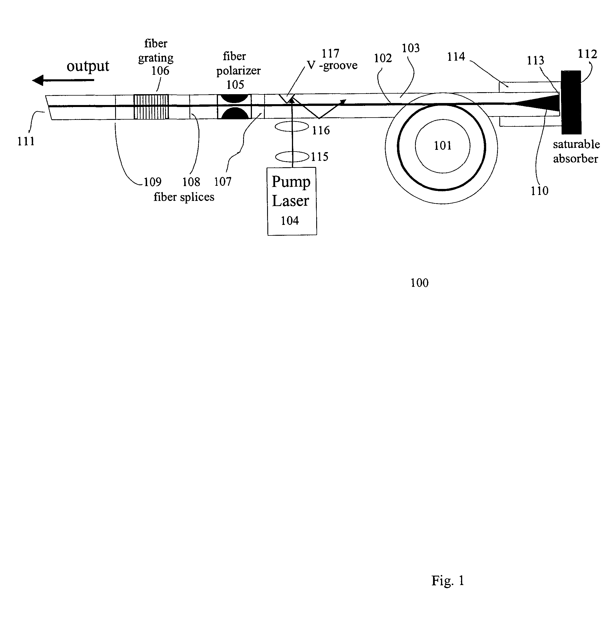
[0046]FIG. 1 represents an exemplary embodiment of the present invention embodied in a fiber laser cavity 100. A polarization-maintaining gain fiber 101 has a core 102 and cladding region 103. The fiber core 102 is doped with rare-earth ions, such as Yb, Nd, Er, Er / Yb, Tm or Pr, to produce gain at a signal wavelength when the laser is pumped with diode laser 104. The fiber core can be single-mode or multi-mode. The fiber laser cavity 100 further contains an integrated fiber polarizer 105 and a chirped fiber Bragg grating 106. Both of these elements, 105 and 106, are generally constructed of short fiber pigtails (e.g., 0.001–1 m in length), which are preferably fusion-spliced to fiber 101 using splices 107, 108 and 109. Alternatively, fiber polarizer 105 can be spliced in front of beam expander 110. When using multi-mode fiber, splice 107 is selected to match the fundamental mode in the gain fiber 101.

[0047]An exemplary integrated fiber polarizer in accordance with the invention comp...


PUM


Abstract

A modelocked linear fiber laser cavity with enhanced pulse-width control includes concatenated sections of both polarization-maintaining and non-polarization-maintaining fibers. Apodized fiber Bragg gratings and integrated fiber polarizers are included in the cavity to assist in linearly polarizing the output of the cavity. Very short pulses with a large optical bandwidth are obtained by matching the dispersion value of the fiber Bragg grating to the inverse of the dispersion of the intra-cavity fiber.

Description

FIELD OF THE INVENTION[0001]This invention relates to modelocked fiber lasers and more particularly an ultra-compact integrated fiber laser with pulse width control in conjunction with concatenated sections of polarization maintaining and non-polarization maintaining fiber sections.BACKGROUND OF THE INVENTION[0002]Modelocked fiber lasers are increasingly displacing traditional solid-state lasers in ultrafast optic applications. Modelocked fiber lasers can be packaged in very small spaces and also exhibit superior mechanical and thermal stability. In particular, passively modelocked fiber lasers allow compact designs because of the absence of bulky optical modulators. Fiber laser systems are pumped using diode lasers with an emission wavelength shorter than the fiber laser emission wavelength. For upconversion-type fiber lasers, the pump wavelength can be longer than the emission wavelength. Generally, similar to the majority of all laser systems, the pump wavelength differs from the...

Claims


Application Information

Patent Timeline
Patent Type & Authority Patents(United States)
IPC IPC(8): H01S5/00H01LH01S3/00H01S3/067H01S3/08H01S3/094H01S3/0941H01S3/098H01S3/1055H01S3/127H01S3/30
CPCH01S3/06708H01S3/1118H01S3/0941H01S3/005H01S3/06712H01S3/1055H01S3/094019
Inventor FERMANN, MARTIN E.CHO, GYU C.
Owner IMRA AMERICA
Why Eureka
Try Eureka