
Method of forming optical fiber preforms

a technology of optical fiber and preforms, which is applied in the direction of glass fibre products, indirect carbon-dioxide mitigation, domestic applications, etc., can solve the problem of one-half mole of combustion supporting oxygen required to combust, and achieve the effects of improving the burning rate, heat and structure of the flame, and increasing the burning speed of the substantially hydrogen-free fuel

Inactive Publication Date: 2006-08-15
BURKE GERALD E +3
View PDF42 Cites 7 Cited by
  • Summary
  • Abstract
  • Description
  • Claims
  • Application Information

AI Technical Summary

Benefits of technology

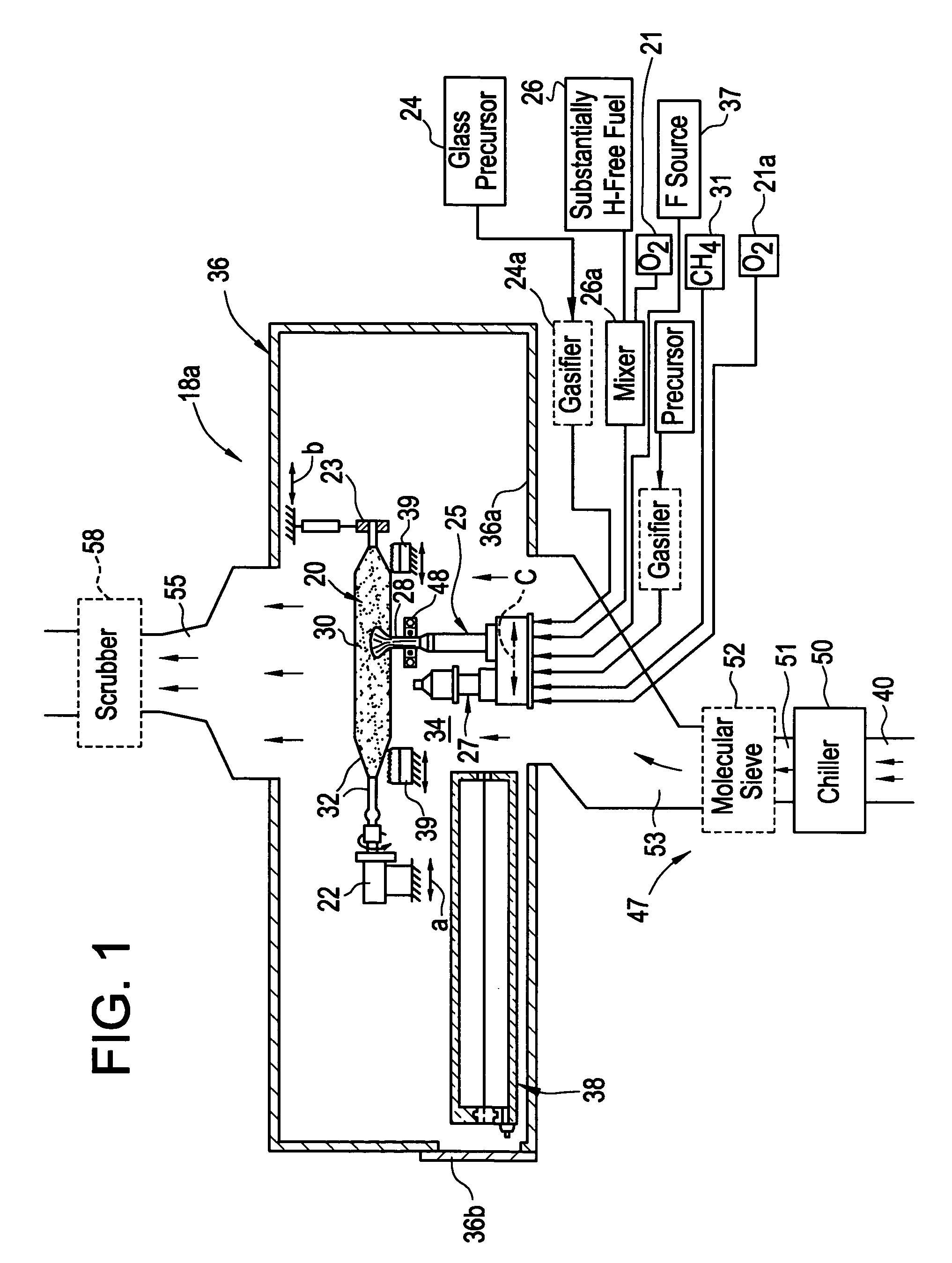
[0015]In another embodiment of the invention, a method of manufacturing a silica-containing soot preform is provided comprising a step of heating at least one end of the preform with at least one end burner wherein the at least one end burner combusts a substantially hydrogen-free fuel. It should be recognized that utilizing end burners that combust a substantially hydrogen-free fuel also minimizes incorporation of water into the preform. Advantageously, these end burners may be utilized in combination with the substantially H-free fuel provided to the soot-producing burner as well as in combination with providing a substantially water-free environment.
[0016]According to another embodiment of the invention, a method of manufacturing an optical fiber preform is provided wherein a combination of conventional deposition methods (using hydrogen-containing fuels) and substantially dry deposition methods are employed. In particular, a first combustion burner generates heat from a first flame produced by igniting a hydrogen-containing fuel or a substantially hydrogen-free fuel. A first glass precursor is flowed into the first flame to lay down a first segment of silica-containing soot within the preform. Next, heat from a second combustion burner having a second flame produced by igniting the other one of the hydrogen-containing fuel, and the substantially hydrogen-free fuel is produced. A second glass precursor is flowed into the second flame to lay down a second segment of silica-containing soot. In this way, a multiple-segment preform may be efficiently manufactured in a single lathe without having an intermediate consolidation step. This so-called single step method of forming a preform has long been sought after in the OVD arts. Glassy barrier layers, as will be described in detail herein, are preferably employed to minimize migration of water or a dopant between the segments. Moreover, glassy barrier layers may aid in the loss of F during consolidation.
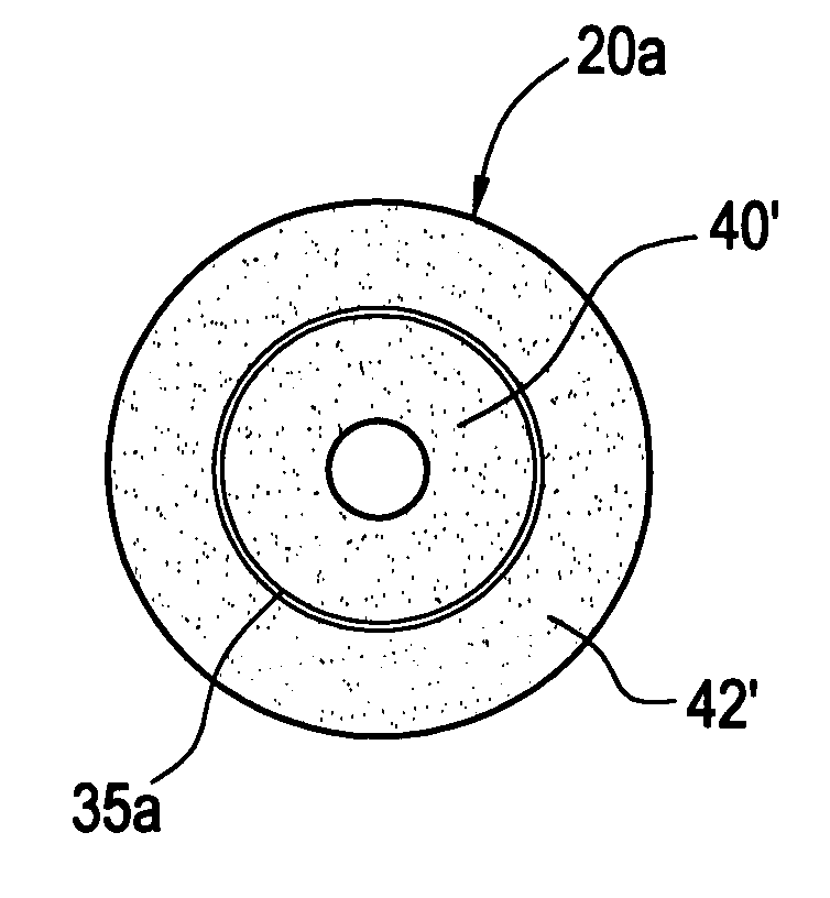
[0017]In accordance with another embodiment of the invention, a method of manufacturing an optical fiber preform having at least one glassy barrier layer is provided. The glassy barrier layer is a thin layer of vitrified or partially vitrified glass that minimizes migration of a dopant or water within the preform. In a preferred embodiment, a first soot segment is formed. A first portion of the first soot segment is then vitrified to form the at least one glassy barrier layer. Additionally, prior to consolidation of a remaining portion of the first soot segment, a second soot segment may be deposited on the at least one glassy barrier layer. Multiple glassy barrier layers may also be utilized within a preform.
[0020]In accordance with another embodiment of the invention, a method of forming a silica-containing soot is provided wherein a chlorine, fluorine, and silica containing glass precursor is reacted. According to the method, the silica-containing soot is generated by reacting, preferably in a flame, a chlorine, fluorine, and silica containing compound in a deposition (laydown) process. The reaction results in generation of a fluorinated silica-containing soot. Most preferably, the chlorine, fluorine, and silica-containing compound comprises a chlorofluorosilane. Exemplary embodiments include SiCl3F, SiCl2F2, or SiClF3. In a preferred embodiment, the chlorine, fluorine, and silica containing compound is mixed in gaseous form with a dilutent gas prior to the step of reacting thereby readily enabling the control of the amount of fluorine contained in the soot.
[0023]In accordance with another embodiment of the invention, a method of producing a fluorine-doped article is provided. The method comprises the step of depositing fluorinated, silica-containing soot containing greater than 0.5% by weight of fluorine by supplying into a flame, in an amount less than 0.5 liters / minute, a fluorine or a fluorine-containing compound. According to this embodiment, efficient incorporation of fluorine onto the soot preform is accomplished. Preferably, the fluorine is included in the silica-containing soot in an amount greater than 1% by weight. The fluorine or fluorine-containing compound may be supplied from an expelling element into the flame or incorporated directly in a fluorine-containing glass precursor, for example, chlorofluorosilane. Most preferably, the flame combusts a substantially hydrogen-free fuel, such as carbon monoxide or the other substantially-hydrogen free fuels, and the fluorine-doped soot is formed within a substantially water-free atmosphere.
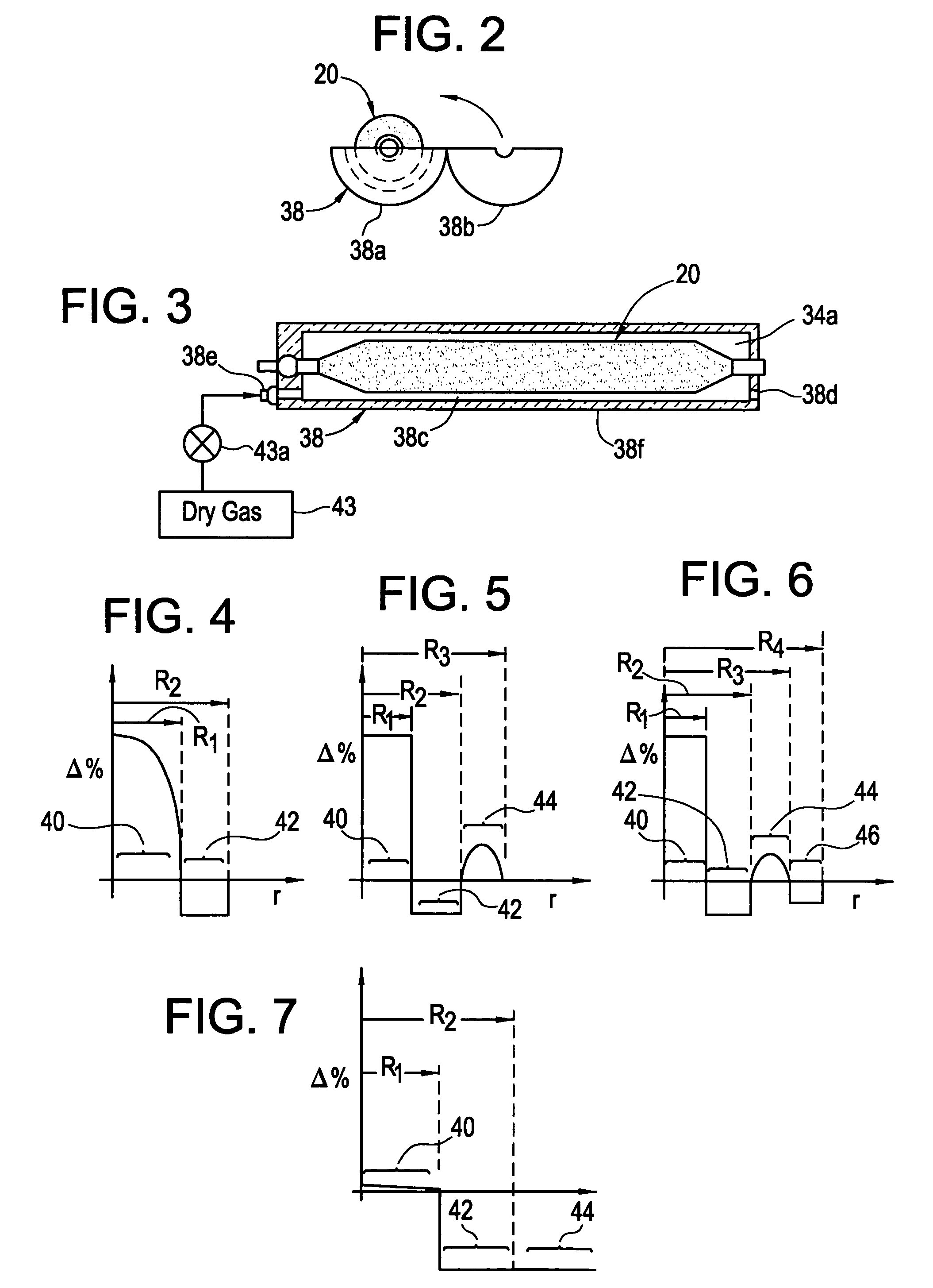
[0024]According to another embodiment of the invention, a method of manufacturing an optical fiber preform is provided. The method includes a step of depositing soot onto a substrate within a substantially water-free atmosphere. The substantially water-free atmosphere preferably is dried air containing less than about 1000 ppm water vapor, more preferably less than 100 ppm water vapor, more preferably less than 10 ppm water vapor, more preferably yet less than 3 ppm water vapor, and most preferably less than 1 ppm water vapor. The substantially water-free atmosphere may be dry nitrogen, dry argon, dry helium, or combinations thereof or dry oxygen, dry carbon dioxide, or combinations thereof. In accordance with another measure, the substantially water-free environment preferably comprises less than 1% relative humidity at a temperature range between about −67° C. and about 125° C. It should be recognized that any significant reduction in the atmospheric water supplied to the preform may advantageously reduce the length of later drying steps.

Problems solved by technology

However, only one-half mole of combustion supporting oxygen is required to combust one mole of CO.

Method used


Image

  • Method of forming optical fiber preforms
  • Method of forming optical fiber preforms
  • Method of forming optical fiber preforms

Examples


example i

Prior Art

[0119]In the OWG process, silica particles generated in flame are deposited on a colder target as amorphous or semi-sintered silica particles. The raw material for silica is OMCTS and the fuel used in natural gas. The blank thus formed is high in water-content. The blank is consolidated in the presence of fluorine to dry the fused silica glass formed. The blank after consolidation typically has a diameter of 4″ and has index of refraction striation that appears as annular rings. To make larger product, a piece of the blank has to be heated to softening temperature and allowed to flow out. This introduces another step to manufacturing and an opportunity to introduce contaminants in the glass.

[0120]The sensible heat released in the methane reaction of Prior Art Equation III is 802.4 kJ that under adiabatic conditions (no energy loss) will be used to heat up 3 moles of products formed. Prior Art Equation IV, the sensible heat released per mole of the product is 267.5 kJ.

example ii

[0121]The sensible heat released by the combustion of carbon monoxide to carbon dioxide, Equation I, is 283 kJ that under adiabatic conditions is used to heat one mole of product of combustion. The heat released from the combustion of one mole is CH4 is approximately three times that released from one mole of CO. The compensate for the lower heating value of CO, the flow rates of CO have to be at least three times higher to have similar heat release in the furnace. Because the heat released per unit mole of product of combustion during combustion of both methane and carbon monoxide are similar, the adiabatic flame temperatures for CO and CH4 are expected to be similar. The adiabatic flame temperature of CO in air is 1950° C. and that for methane is 1941° C. Adiabatic flame temperatures in oxygen are much higher as the thermal load due to the excess nitrogen in air is eliminated. The adiabatic flame temperature for CH4 in oxygen is 2643° C. The adiabatic flame temperature for CO in o...

example iii

[0122]The run conditions for the glass were as follows. This glass was made using a single liquid feed burner. The SiCl4 flow was between 5.5 and 7.5 g / min. Oxygen was used as an atomizing gas at 25 slpm. The CO gas stream was at 50 slpm. The distance at the start of the run from furnace crown to the sand was 9 inches and the crown temperature was maintained at about 1670° C.

[0123]As a result, this enables the manufacture of water-free fused silica glass by eliminating the use of any hydrogen containing reactants, both as raw material for silica and as fuel, the products of combustion have been made substantially water-free. Further, wet natural gas may be a source for sodium in addition to the water it carries. By eliminating the use of natural gas from the process, another possible source of contamination has been removed. The major hindrance to achieving high transmission at low wavelengths is iron contaminant. Fortunately, carbon monoxide combines readily with metals and in part...


PUM

PropertyMeasurementUnit
thicknessaaaaaaaaaa
thicknessaaaaaaaaaa
thicknessaaaaaaaaaa

Abstract

Methods, apparatus and precursors for producing substantially water-free silica soot, preforms and glass. The methods and apparatus make substantially water-free fused silica preforms or glass by removing water as a reaction product, removing water from the atmosphere, removing water from the transport process, or combinations thereof. In a first embodiment, substantially water-free soot, preforms or glass are achieved by using a hydrogen-free fuel, such as carbon monoxide, in the deposition process. In another embodiment, a soot producing burner has parameters that enable operation on a substantially hydrogen-free fuel. End burners, which minimize water production, are also described. Such water-free methods are useful in depositing fluorine-doped soot because of the low water present and the efficiency in which fluorine is incorporated. In another embodiment, glassy barrier layer methods and apparatus are described for minimizing dopant migration, especially fluorine. Laser and induction methods and apparatus for forming the barrier layer are depicted. A chlorine, fluorine and silica precursor, such as chlorofluorosilane, may be utilized to form fluorinated soot. Other methods and apparatus are directed to combinations of conventional and substantially water-free processes. One embodiment is directed to combustion enhancing additives for addition to the substantially hydrogen-free fuels. The methods and apparatus in accordance with the invention are particularly useful for producing photomask substrates and optical fiber preforms.

Description

RELATED APPLICATIONS[0001]This application is a divisional application and claims priority to U.S. application Ser. No. 09 / 833,540, filed Apr. 11, 2001, now abandoned, which is titled “SUBSTANTIALLY DRY SILICA-CONTAINING SOOT, FUSED SILICA AND OPTICAl. FIBER SOOT PREFORMS, APPARATUS, METHODS AND BURNERS FOR MANUFACTURING THE SAME”. This application also claims priority to, and the benefit to U.S. Provisional Patent Application No. 60 / 200,405 filed Apr. 28, 2000 entitled “Water-Free Fused Silica And Method Therefor,” and U.S. Provisional Patent Application 60 / 258,132 filed Dec. 22, 2000 entitled “substantially Dry, Silica-containing Soot, Fused Silica And Optical Fiber Soot Preforms, Apparatus, Methods And Burners For Manufacturing Same And Method Therefor,” the disclosure of which are hereby incorporated by reference herein.TECHNICAL FIELD[0002]This invention relates to methods and apparatus for producing optical fiber soot preforms, high purity fused silica and silica-containing so...

Claims


Application Information

Patent Timeline
Patent Type & Authority Patents(United States)
IPC IPC(8): C03B37/018C03B37/029C03B19/14C03B37/012C03B37/014C03C3/06F23D14/22F23D14/32G03F1/00G03F7/20
CPCC03B19/1407C03B19/1423C03B19/1453C03B37/01202C03B37/01406C03B37/01413C03B37/0142C03B37/0146C03C3/06F23D14/22F23D14/32G03F1/14G03F7/70216G03F7/70958C03B19/1415C03B2207/81C03B2201/12C03B2203/22C03B2207/02C03B2207/06C03B2207/08C03B2207/14C03B2207/20C03B2207/30C03B2207/38C03B2207/40C03B2207/42C03B2207/46C03B2207/54C03B2207/70C03C2201/12C03C2201/20C03C2201/23C03C2201/30C03C2201/32Y02E20/344G03F1/60C03B37/018
Inventor BURKE, GERALD E.DAWES, STEVEN B.SRIKANT, V.TANDON, PUSHKAR
Owner BURKE GERALD E
Learn More