Transmission circuit

a transmitter circuit and circuit technology, applied in the field of circuits for transmitters of radio communications, can solve the problems of limited bandwidth of amplitude modulated voltage and phase modulated signals, inability to unlimitedly widen the frequency band where bandwidth is limited, and still deterioration of modulated signals, so as to suppress the spectrum of modulated signals, enhance the operation speed of the circuit and the required frequency characteristics, and suppress the effect of modulated signal spectrum deterioration

Active Publication Date: 2006-08-15
GK BRIDGE 1
View PDF9 Cites 39 Cited by
  • Summary
  • Abstract
  • Description
  • Claims
  • Application Information

AI Technical Summary

Benefits of technology

[0023]Then, unnecessary power densities at frequencies at large distances from the center frequency of the modulated signal are suppressed, so that it is possible to suppress deterioration of the spectrum of the modulated signal to be transmitted while not extremely widening the frequency band where the bandwidth of the phase modulated signal is limited. Accordingly, a transmission circuit in an appropriate scale is implemented without extremely enhancing the operation speed of the circuit and...

Problems solved by technology

However, the conventional transmission circuits have the following drawbacks.
On the other hand, because of removal of a frequency aliasing component output by a sampling system of digital signal processing or frequency characteristics of analog circuits, the bandwidths of the amplitude modulated voltage and the phase modulated signal are limited.
However, in the conventional transmission circuit, even if th...

Method used


Image

  • Transmission circuit
  • Transmission circuit
  • Transmission circuit

Examples


embodiment 1

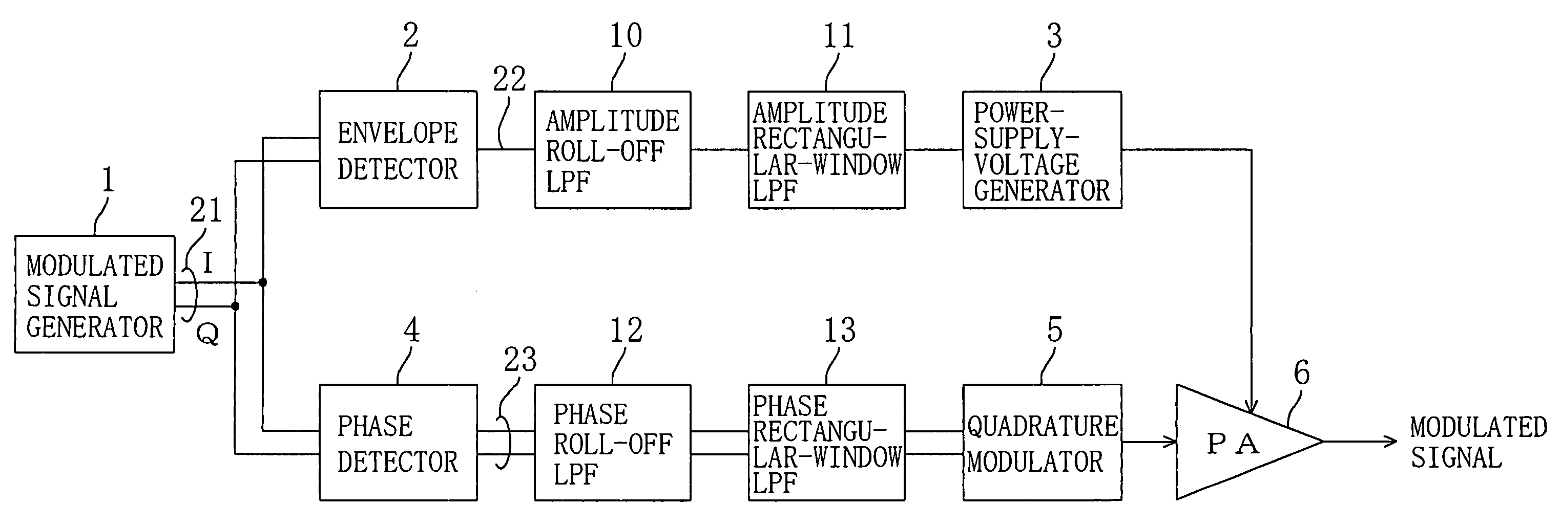
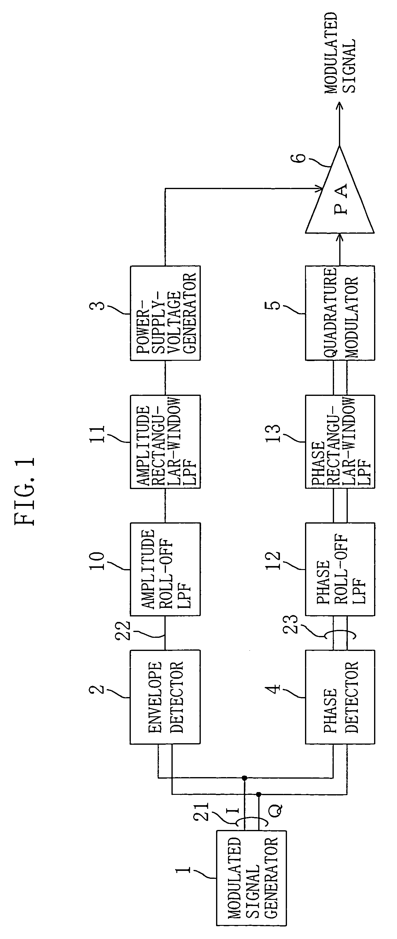
[0039]FIG. 1 is a block circuit diagram showing a transmission circuit according to a first embodiment of the present invention. As shown in FIG. 1, the transmission circuit of this embodiment includes: a modulated signal generator 1 for outputting a modulated signal; modulated signal lines 21 each divided into two branches and used for transmitting a modulated signal; an envelope detector 2 connected to the branches at one side of the respective modulated signal lines 21, receiving the modulated signal to detect the envelope of the signal and outputting an amplitude modulated voltage (an amplitude component); an amplitude modulated voltage line 22 extending from the envelope detector 2; an amplitude roll-off low-pass filter (LPF) 10 interposed in the amplitude modulated voltage line 22, receiving the amplitude modulated voltage output from the envelope detector 2 and performing bandwidth limitation on the received voltage; an amplitude rectangular-window LPF 11 interposed in the am...

third specific example

[0067]Now, a third specific example in which the amplitude bandwidth limiting means of the first specific example and the phase bandwidth limiting means of the second specific example are used will be described.

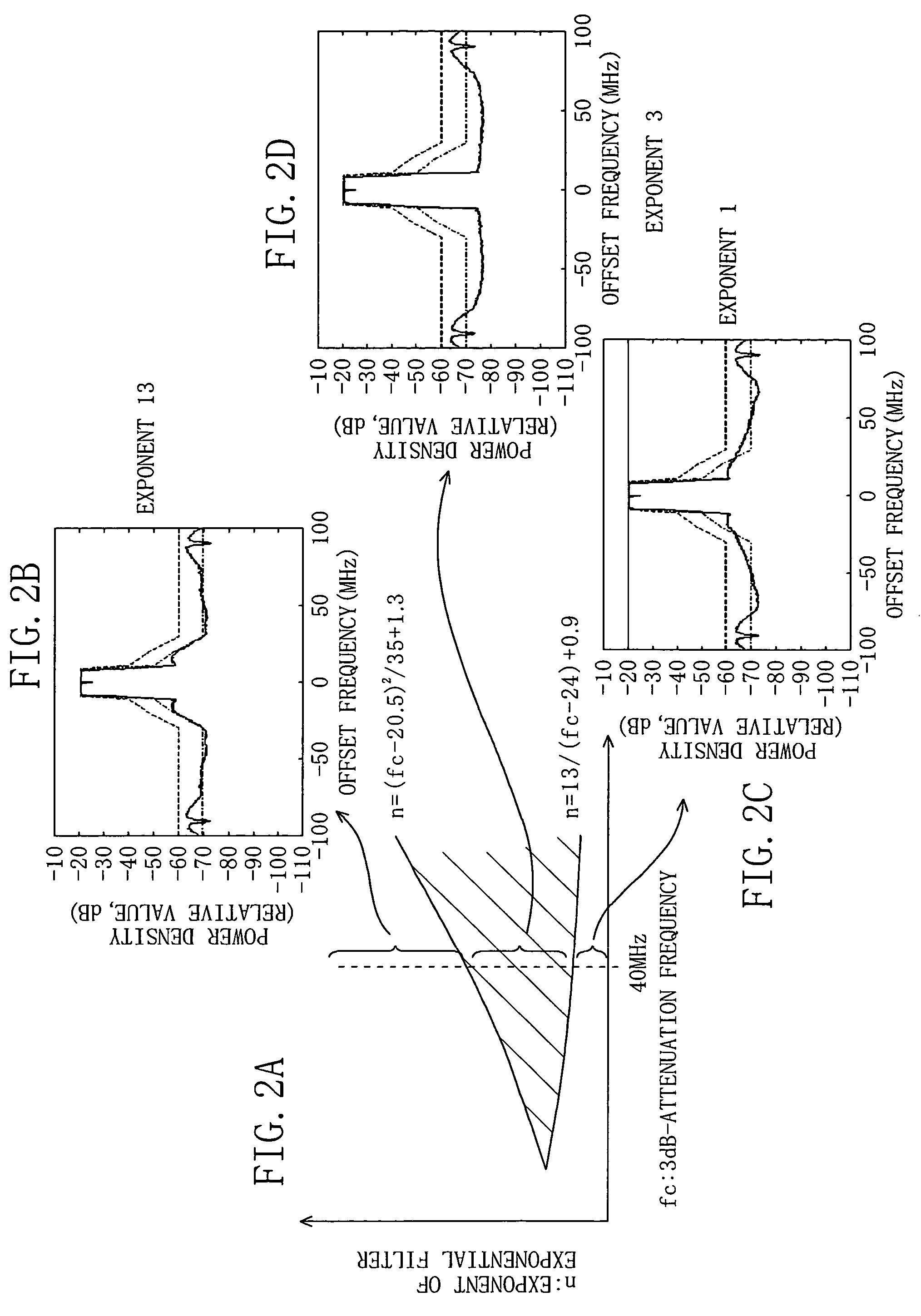
[0068]FIGS. 4A through 4C are graphs showing simulation results of a modulated signal in the respective cases where only the exponential filter of the first specific example is used, where only the exponential filter of the second specific example is used, and where the exponential filters of the first and second specific examples are used. FIG. 4A shows the same characteristic as that shown in FIG. 2D. FIG. 4B shows the same characteristic as that shown in FIG. 3C.

[0069]In FIG. 4C, the power density is attenuated noticeably in ranges where the offset frequency is large and thus the bandwidth limiting function is enhanced in these ranges as compared to the first and second examples.

[0070]The cutoff frequency (70 MHz) of the amplitude rectangular-window LPF 11, i.e., the cutof...

fourth specific example

[0071]Now, a fourth specific example in which a filter in a special case where exponent n or m in the first, second or third specific example is two, i.e., a so-called Gaussian filter, is used for each of the amplitude bandwidth limiting means and the phase bandwidth limiting means will be described. It should be noted that the amplitude roll-off LPF satisfies

13 / {(16.6fc / fop)−24}+0.9≦n≦{(16.6fc / fop)−20.5}2 / 35+1.3

and the phase roll-off LPF satisfies

0≦m≦3.5 exp[0.0615{(16.6fc / fop)−30}]

[0072]FIGS. 5A through 5C are graphs showing simulation results of a modulated signal in the respective cases where only a Gaussian filter is used in the first specific example, where only a Gaussian filter is used in the second specific example, and where a Gaussian filter is used in third specific example.

[0073]Suppose the characteristics of the amplitude roll-off LPF and the phase roll-off LPF are within respective appropriate areas, if n (or m) is two as shown in FIGS. 5A and 5B, an excellent spectru...


PUM


Abstract

A transmission circuit includes: a modulated signal generator for outputting a modulated signal; an envelope detector for outputting an amplitude modulated voltage; an amplitude roll-off LPF for attenuating the amplitude modulated voltage by using a damping property represented by an exponential function in which an argument is exponentially proportional to a frequency; a power-supply-voltage generator for generating a power supply voltage in accordance with an amplitude value of the amplitude modulated voltage; a phase detector for outputting a phase modulated signal; a phase roll-off LPF for attenuating the phase modulated signal by using a damping property represented by an exponential function in which an argument is exponentially proportional to an offset frequency with respect to a center frequency; and an RF power amplifier.

Description

BACKGROUND OF THE INVENTION[0001]The present invention relates to circuits for transmitters of radio communications, below denoted as “transmission circuits”.[0002]In general, to process modulated signals with amplitude modulation, especially multiple modulation such as Quadrature Amplitude Modulation (QAM), radio-frequency power amplifiers in transmission circuits for transmitting power to antennas need linear amplification. Therefore, class A or AB had been adopted as operation classes of the RF power amplifiers.[0003]However, with the progress of broadband communication, communication methods using subcarrier modulation such as Orthogonal Frequency Division Multiplex (OFDM) have come to be used and high efficiency is not expected any more with the conventional class-A or AB radio frequency amplifiers. That is, in the OFDM modulation, subcarriers are overlapped so that a large amount of power is instantaneously generated at random time and the ratio between the average power and t...

Claims


Application Information

Patent Timeline
IPC IPC(8): H04B1/02H04B1/04
CPCH04B1/0475
Inventor TANAKA, KOICHIROTANABE, MITSURUSAITO, NORIAKI
Owner GK BRIDGE 1
Why Eureka
Try Eureka