Modular design for downhole ECD-management devices and related methods

a module design and management device technology, applied in the direction of borehole/well accessories, sealing/packing, vessel construction, etc., can solve the problems of increasing the pressure which can fracture the formation, severely restricting the ability to clean the hole, and limiting the rate of circulation. achieve the effect of improving system life, reducing sub-optimal operation, and enhancing drilling efficiency

a module design and management device technology, applied in the direction of borehole/well accessories, sealing/packing, vessel construction, etc., can solve the problems of increasing the pressure which can fracture the formation, severely restricting the ability to clean the hole, and limiting the rate of circulation. achieve the effect of improving system life, reducing sub-optimal operation, and enhancing drilling efficiency

US7096975B2Inactive Publication Date: 2006-08-29BAKER HUGHES INC

Image

  • Modular design for downhole ECD-management devices and related methods
  • Modular design for downhole ECD-management devices and related methods
  • Modular design for downhole ECD-management devices and related methods

Examples


Embodiment Construction

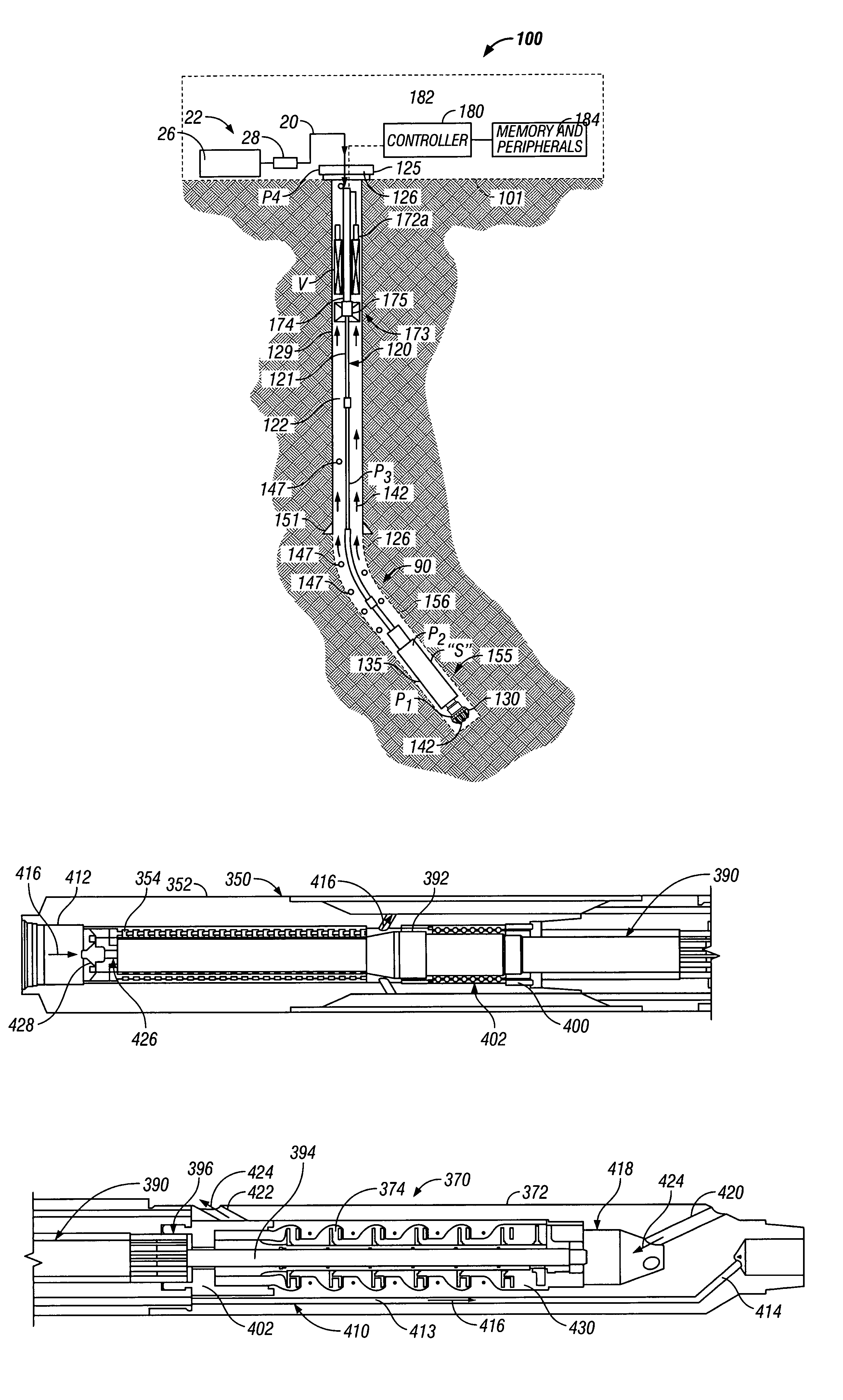
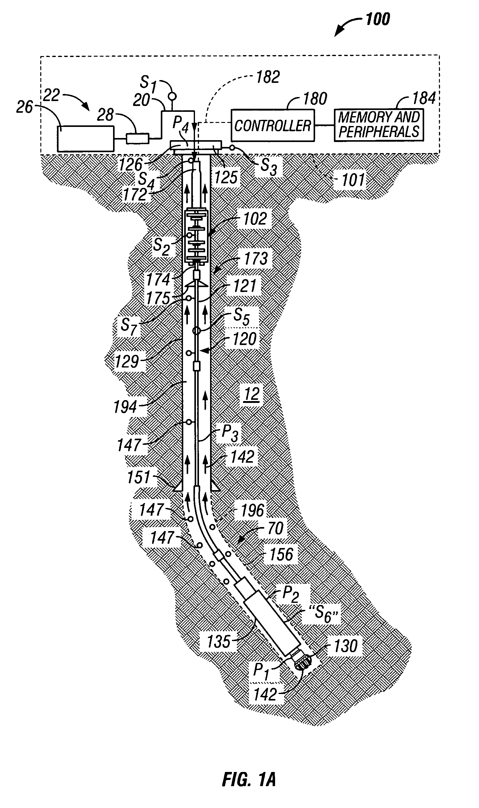
[0035]Referring initially to FIG. 1A, there is schematically illustrated a system for performing one or more operations related to the construction, logging, completion or work-over of a hydrocarbon producing well. In particular, FIG. 1A shows a schematic elevation view of one embodiment of a wellbore drilling system 100 for drilling wellbore 90 using conventional drilling fluid circulation. The drilling system 100 is a rig for land wells and includes a drilling platform 101, which may be a drill ship or another suitable surface workstation such as a floating platform or a semi-submersible for offshore wells. For offshore operations, additional known equipment such as a riser and subsea wellhead will typically be used. To drill a wellbore 90, well control equipment 125 (also referred to as the wellhead equipment) is placed above the wellbore 90. The wellhead equipment 125 includes a blow-out-preventer stack 126 and a lubricator (not shown) with its associated flow control.

[0036]This...


PUM


Abstract

One or more components of a wellbore drilling assembly utilize a modular construction to facilitate assembly, disassembly, repair and / or maintenance of a wellbore drilling assembly and / or to extend the overall operating capabilities of the drilling assembly. In one embodiment, a modular construction is used for an APD Device, a motor driving the modular APD Device, a comminution device, and an annular seal. Individual modules can be configure have different operating set points, operating parameters and characteristics (e.g., rotational speeds, flow rates, pressure differentials, etc.) and / or different responses to given environmental factors or conditions (e.g., pressure, temperature, wellbore fluid chemistry, etc.). In one embodiment, the high-pressure seals used in conjunction with the APD Device and / or motor is a hydrodynamic seal that provides a selected leak or flow rates. Optionally, the seal is modular to provide different degrees of leak rates and / or different functional characteristics.

Description

CROSS-REFERENCE TO RELATED APPLICATIONS[0001]This application is a continuation-in-part of U.S. patent application Ser. No. 10 / 783,471 filed Feb. 20, 2004, which is a continuation of U.S. patent application Ser. No. 10 / 251,138 filed Sep. 20, 2002, now abandoned, which takes priority from U.S. provisional patent application Ser. No. 60 / 323,803 filed on Sep. 20, 2001, titled “Active Controlled Bottomhole Pressure System and Method.”[0002]This application is a continuation-in-part of U.S. patent application Ser. No. 10 / 716,106 filed on Nov. 17, 2003, now U.S. Pat. No. 6,854,532, which is a continuation of U.S. patent application Ser. No. 10 / 094,208, filed Mar. 8, 2002, now U.S. Pat. No. 6,648,081 granted on Nov. 18, 2003, which is a continuation of U.S. application Ser. No. 09 / 353,275, filed Jul. 14, 1999, now U.S. Pat. No. 6,415,877, which claims benefit of U.S. Provisional Application No. 60 / 108,601, filed Nov. 16, 1998, U.S. Provisional Application No. 60 / 101,541, filed Sep. 23, 199...

Claims


Application Information

Patent Timeline
29 Aug 2006
Publication
US7096975B2
IPC
E21B21/08; B63B21/50; E21B7/00; E21B7/12; E21B7/128; E21B7/28; E21B17/20; E21B19/00; E21B19/09; E21B19/22; E21B21/00; E21B33/076; E21B43/12
CPC
B63B21/502; E21B7/128; E21B7/28; E21B17/206; E21B19/002; E21B19/09; E21B19/22; E21B21/00
Inventors
ARONSTAM, PETER; KRUEGER, VOLKER