Ceramic-rich composite armor, and methods for making same

a composite armor and ceramic technology, applied in the field of ballistic armor structures, can solve the problems of reaction-bonded silicon carbide, high cost of hot pressing and shape limitation, and the ability to resist the attack of armor, and achieve the effect of less expensive processing and minimal dimensional chang

Inactive Publication Date: 2006-09-12
II VI DELAWARE INC
View PDF36 Cites 50 Cited by
  • Summary
  • Abstract
  • Description
  • Claims
  • Application Information

AI Technical Summary

Benefits of technology

[0023]It is an object of the instant invention to produce a lightweight composite material that has utility as armor against ballistic projectiles, and specifically to engineer a ceramic-rich composite as an armor material.
[0030]Reaction-bonded silicon carbide composite bodies arc generally cheaper to manufacture than hot pressed silicon carbide bodies. Additionally, the instant RBSC composite materials maintain their size and shape better than do hot pressed silicon carbide bodies, as expressed or measured by dimensional tolerances. The ability to make ceramic armor plates having complex shaped curves that faithfully reproduce the desired shape can have significant value in meeting the form and fit requirements of the armor purchaser. Typically, armor for weight sensitive applications is specified for purchase in terms of meeting some minimum ballistic performance parameter and meeting some maximum weight or areal density. Because the objective is high ballistic performance and low areal density, both of which parameters are related to thickness but trending in opposite directions, one wants as uniform a thickness to the armor as possible. Thus, this potential of RBSC to produce highly dimensionally accurate shaped articles makes it well-suited for use in the production of armor.DEFINITIONS

Problems solved by technology

Thus, where brittle materials like ceramics are concerned, it is important to try to prevent brittle fracture due to excessive tensile stresses on the back face of the armor body; otherwise, the armor is too easily defeated.
Hot pressing is expensive and shape-limited.
Hot pressed or sintered ceramics do not hold dimensional tolerances as well as reaction-bonded silicon carbide (“RBSC”).
An infiltration temperature of 2200° C. is too high, and will likely result in exaggerated grain growth.
A preform containing 35 volume percent of reactable carbon will yield excessive amounts of in-situ SiC.
As for the strength parameter, however, those testing armor materials have had a difficult time correlating mechanical strength (both tensile and compressive) with ballistic performance.

Method used


Image

  • Ceramic-rich composite armor, and methods for making same
  • Ceramic-rich composite armor, and methods for making same
  • Ceramic-rich composite armor, and methods for making same

Examples


example 1

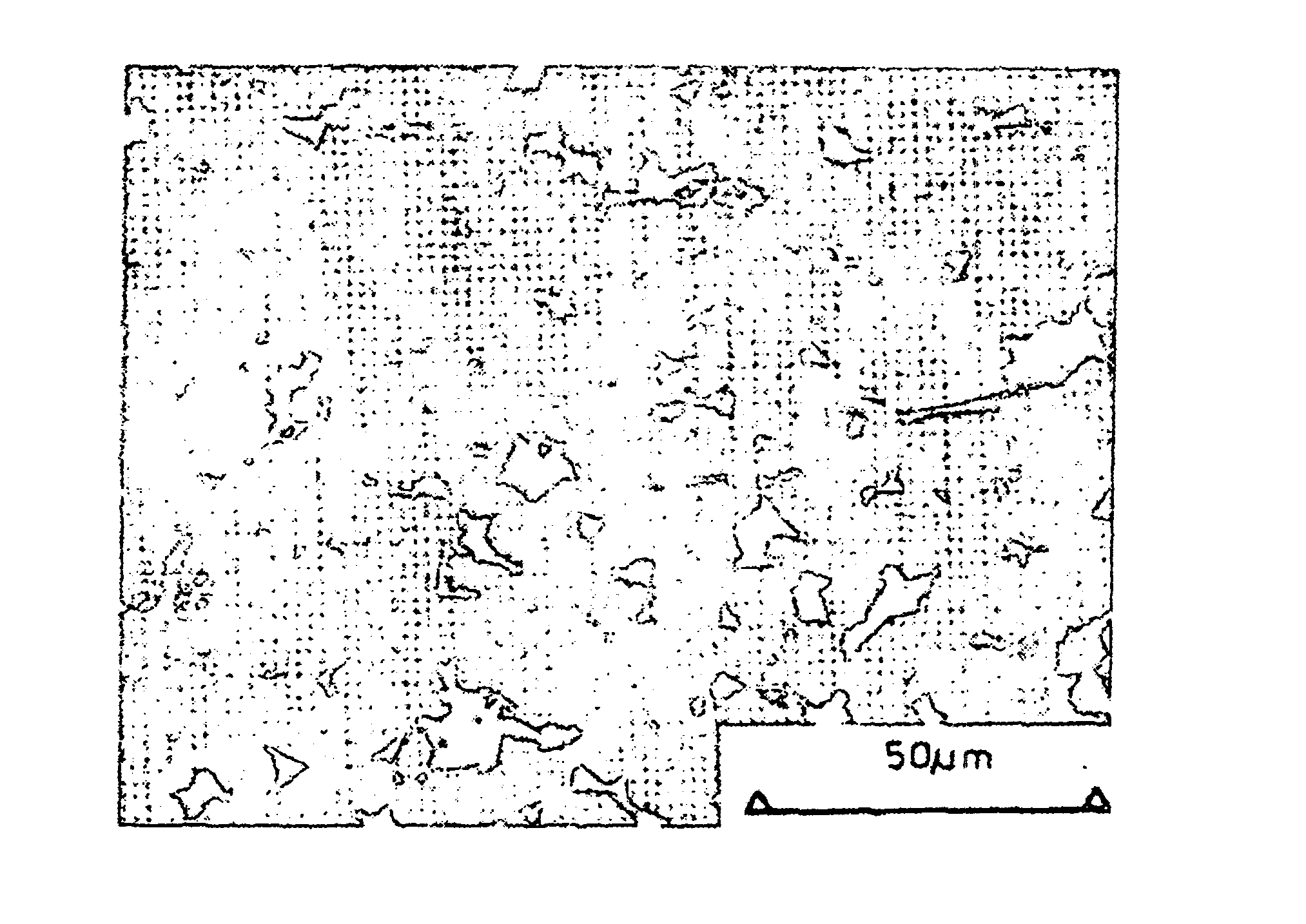
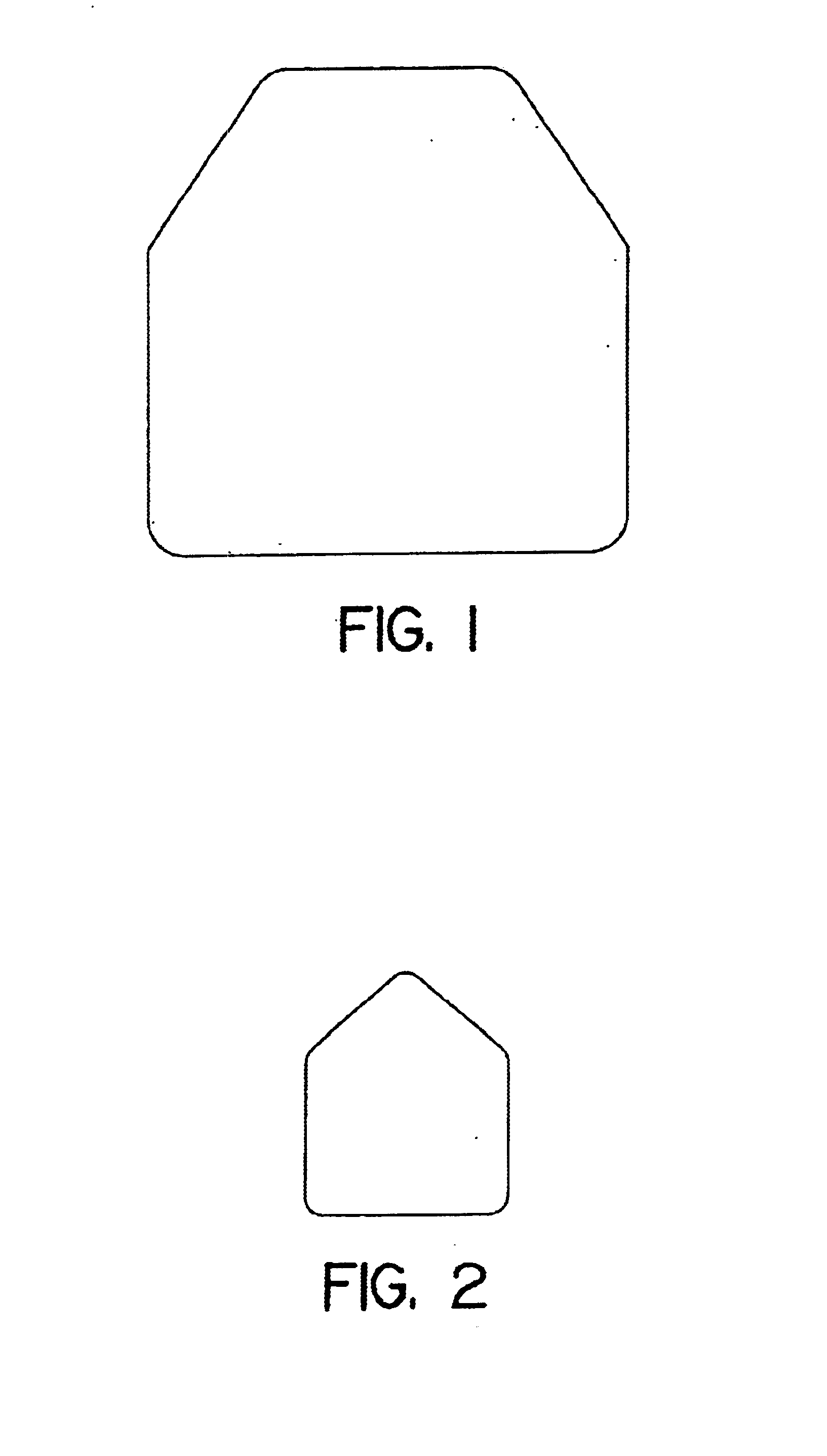
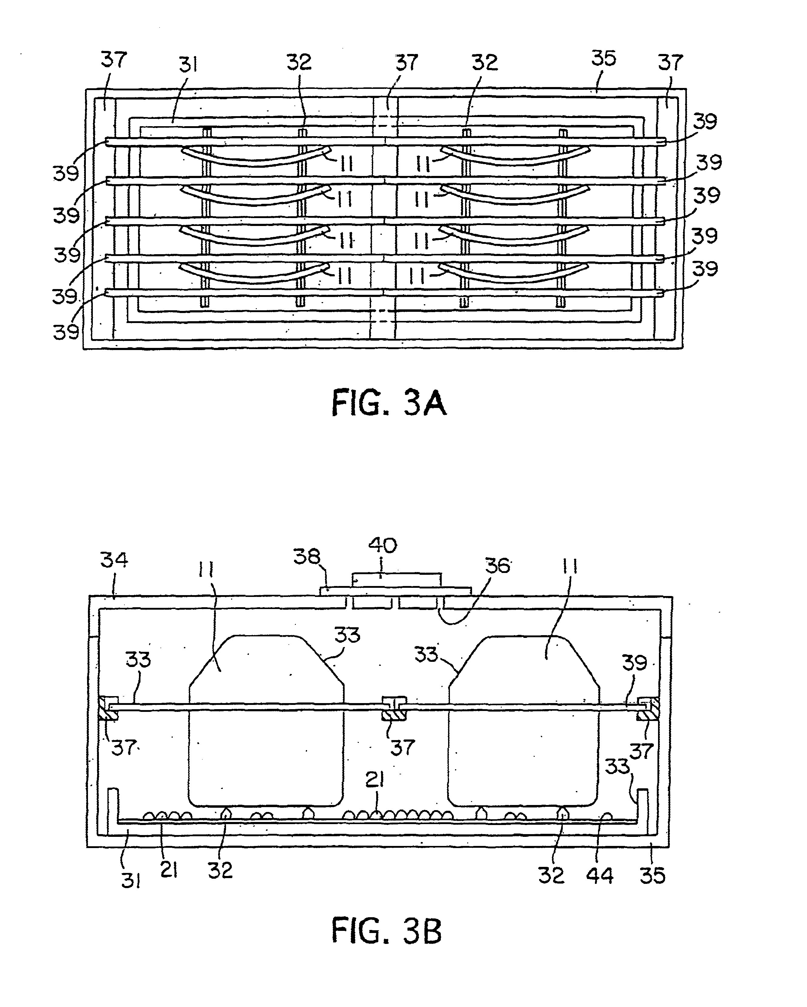
[0089]This example demonstrates, among other important features of the instant invention, the fabrication of a silicon carbide composite armor plate highly loaded in a fine-grained silicon carbide filler.

[0090]An armor “breastplate” and four “feeder rail” preforms were prepared by a sedimentation casting process. Specifically, about 24 parts of de-ionized water were added to 100 parts of CRYSTOLON green silicon carbide (Saint-Gobain / Norton Industrial Ceramics, Worcester, Mass.) and about 6 parts of KRYSTAR 300 crystalline fructose (A.E. Staley Manufacturing Co., Decatur, Ill.) to make a slurry. The silicon carbide particulate consisted of about 65 parts by weight of Grade F320 (median particle size of about 29 microns, blocky morphology) and the balance Grade 500 RG (median particle size of about 13 microns, rounded morphology). The solids and liquids were added to a plastic jar and roll mixed for about 40 hours. The slurry was de-aired in about 760 mm of vacuum for about 5 minutes....

example 2

[0105]Eight silicon carbide composite armor breastplates were formed in substantially the same manner as in Example 1, with the following exceptions. First, about 22 parts by weight of deionized water was added to about 6 parts of KRYSTAR crystalline fructose (A.E. Staley Mfg. Co.) and about 100 parts of CRYSTOLON green silicon carbide particulate (Saint-Gobain / Norton Industrial Ceramics, Worcester, Mass.). Second, the silicon carbide particulate consisted by weight of about 60 percent Grade F240 (median particle size of about 45 microns, blocky morphology) and the balance Grade 500 RG (median particle size of about 13 microns, rounded morphology).

example 3

[0106]Silicon carbide armor breastplates were produced substantially in accordance with Example 2, with the following notable exceptions. First, the back-soaking of fructose solution into the pyrolyzed breastplate preforms was modified somewhat. More exactly, the aqueous solution was about 80 percent by weight of KRYSTAR® crystalline fructose (A.E. Staley Mfg. Co.), and the breastplate preforms were immersed in this solution for a minimum of about 3 hours at ambient pressure only, i.e., with no application of pressure or vacuum to accelerate the back-soaking. Second, the breastplate preforms were not coated with boron nitride. Third, the breastplate preforms were infiltrated with the length dimension instead of the width dimension of the preform in contact with the feeder rails.


PUM

PropertyMeasurementUnit
diameteraaaaaaaaaa
sizeaaaaaaaaaa
temperatureaaaaaaaaaa

Abstract

Silicon infiltration technology, e.g., siliconizing or reaction-bonding, is used to produce ceramic-rich composite bodies having utility as ballistic armor. In the main embodiment of the invention, the ballistic armor includes a reaction-bonded silicon carbide body (RBSC). Good ballistic performance can be advanced by loading the porous mass or preform to be infiltrated to a high degree with one or more hard fillers, and by limiting the size of the morphological features making up the composite body. This control of “grain size” can be accomplished by controlling the size of the largest particles making up the porous mass to be infiltrated, but also of importance is controlling the processing conditions, particularly by controlling the factors that cause grain growth, coarsening of microstructure, and / or grain coalescence.

Description

CROSS-REFERENCE TO RELATED APPLICATIONS[0001]This is a Continuation-in-Part of U.S. patent application Ser. No. 10 / 286,405, filed on Nov. 1, 2002, now U.S. Pat. No. 6,805,034, which is a Divisional of U.S. patent application Ser. No. 09 / 757,826, filed on Jan. 10, 2001, now U.S. Pat. No. 6,609,452 which claimed the benefit of Provisional Application No. 60 / 252,489, filed on Nov. 21, 2000, as well as Provisional Application No. 60 / 175,389, filed on Jan. 11, 2000. The contents of each of these commonly owned patent applications are expressly incorporated herein by reference.BACKGROUND OF THE INVENTION[0002]1. Field of the Invention[0003]This invention relates to ballistic armor structures produced using silicon infiltration technology. More particularly, the invention relates to infiltration techniques to form ceramic-rich composite armor bodies, e.g., reaction-bonded silicon-carbide bodies.[0004]2. Discussion of Related Art[0005]In many armor applications, weight is not a critical fac...

Claims


Application Information

Patent Timeline
Patent Type & Authority Patents(United States)
IPC IPC(8): F41H5/04
CPCF41H5/0428F41H5/0492Y10S428/911C04B35/565C04B35/573C04B2235/5436C04B2235/5472C04B35/62625C04B35/632C04B2235/3826C04B2235/3834C04B37/005C04B2237/363C04B2237/365C04B2237/38C04B2237/385C04B2237/61C04B2235/5256B32B18/00
Inventor AGHAJANIAN, MICHAEL K.MCCORMICK, ALLYN L.
Owner II VI DELAWARE INC
Why Eureka
Try Eureka