Axial flow pump or marine propulsion device

a technology of axial flow and pumping device, which is applied in the direction of positive displacement liquid engine, marine propulsion, vessel construction, etc., can solve the problems of large volume, difficult service, and myriad mechanical problems, and achieve the effect of increasing the static pressure of the working fluid and increasing the velocity of the fluid discharg

Inactive Publication Date: 2006-09-19
CORNELL DONALD E
View PDF15 Cites 12 Cited by
  • Summary
  • Abstract
  • Description
  • Claims
  • Application Information

AI Technical Summary

Benefits of technology

[0009]A first aspect of the invention comprises a multistage axial flow device that includes an outer housing or casing, preferably cylindrical, an substantially annular chamber within said housing to convey a substantially incompressible working fluid (e.g., water) from an inlet to an outlet where each stage includes a rotor section and a stator section positioned downstream of the rotor section. The stator vanes are fixed relative to housing and have a geometrical shape to define a flow path having a cross-sectional area that increases from an entry point to an exit point of the stator section whereby to stepwise increase static pressure of the working fluid at successive stator stages. Optionally, the stator vanes have variable pitch. The discharge nozzle area may also be convergent to increase velocity of fluid discharged from the outlet. In an additional aspect of the invention, the discharge nozzle has a variable area throat, which is controlled to optimally match the speed of the vessel with the water jet discharge speed. In yet a further aspect of the invention, the axial flow device includes a variable inlet guide vane that, among other things, controls or “throttles” inlet fluid flow by changing the inlet area and swirl angle of water entering the inlet. This enables the device to match a wide range of prime movers of different power.

Problems solved by technology

This differs from a conventional centrifugal or mixed-flow pumping device that is generally limited to single stage and consumes a relatively large volume.
Counter-rotating rotors, however, presented myriad mechanical problems and were difficult to service.
Most engines, however, have only one optimum operating speed that delivers peak horsepower or peak efficiency, but the operating speed may not optimally match the desired thrust and / or hull speed of the vessel, which varies with loading of the vessel, fluid density, fluid temperature, or other conditions.
Thus, certain inefficiencies inherently exist in prior power plant-thruster combinations.
The stator vanes had the effect of redirecting fluid flow to maintain a desired angle-of-attack of rotor blades in the succeeding stage while the rotor blades worked against the whirling fluid, but such prior stator vane designs significantly increased internal friction.
It was not known, however, to provide variable pitch stator vanes in prior systems to efficiently compensate for pressure, velocity (propulsor or vessel), or torque fluctuations.
Due to their geometric structure, prior stator vane designs did not maintain or increase static pressure between rotor sections, and therefore, endured other losses in efficiencies.

Method used


Image

  • Axial flow pump or marine propulsion device
  • Axial flow pump or marine propulsion device
  • Axial flow pump or marine propulsion device

Examples


Embodiment Construction

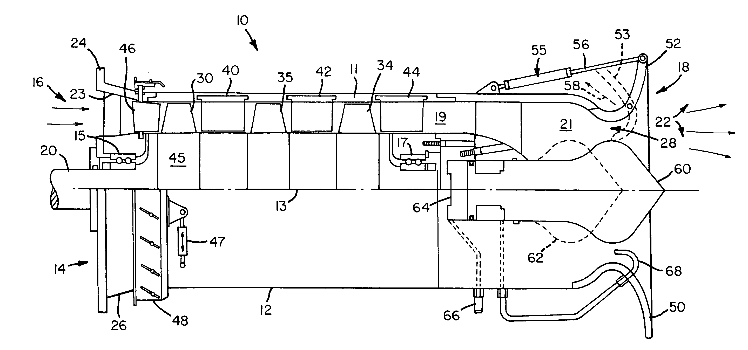
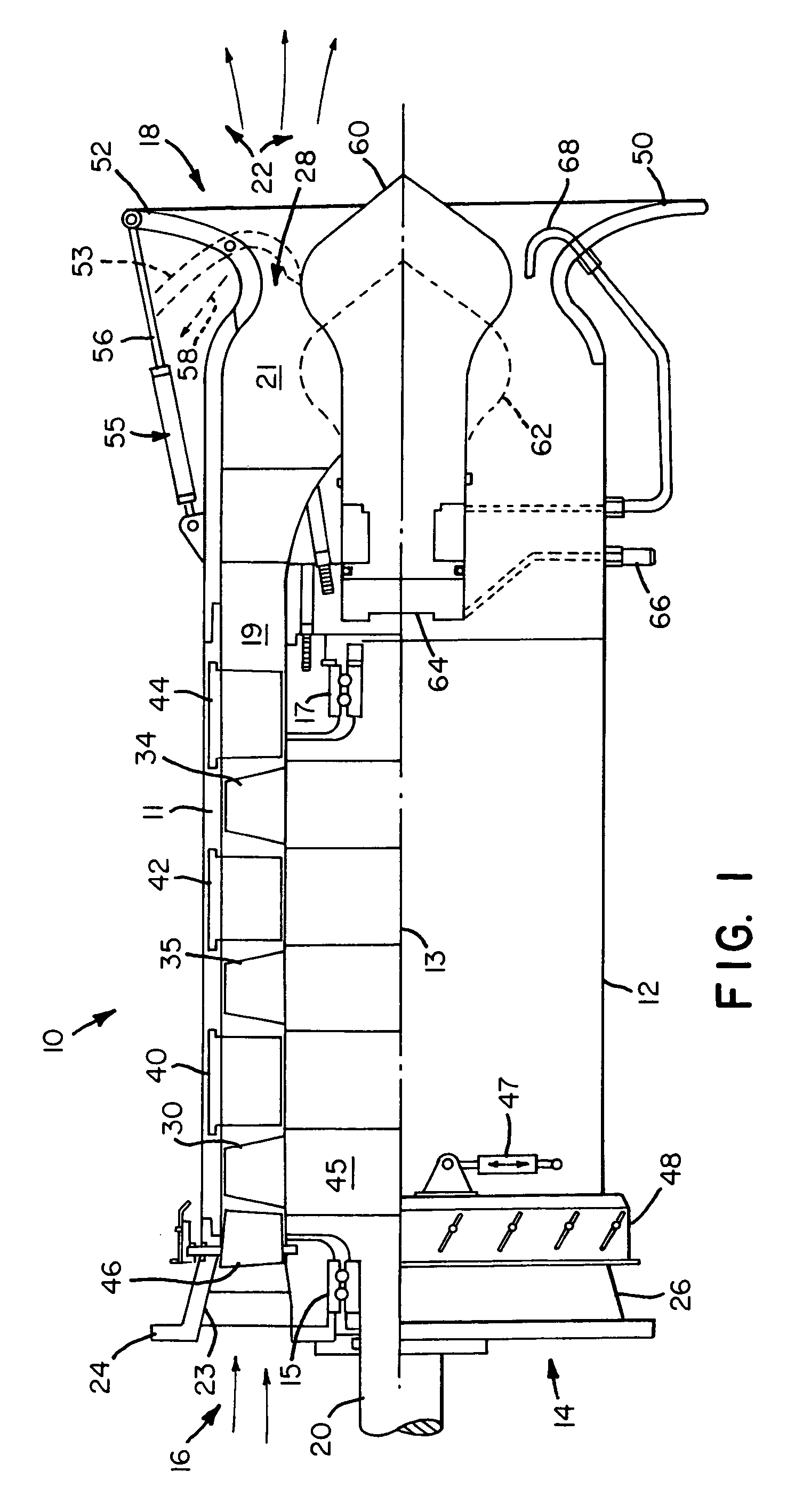
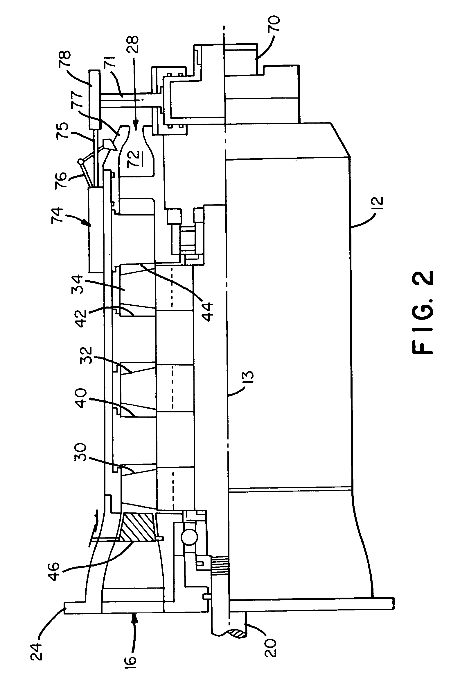
[0029]FIG. 1 shows a first embodiment of a pumping or propulsion device 10 having a substantially cylindrical outer casing 12, an inlet 14 through which a substantially incompressible working fluid (e.g., sea water) enters, and an outlet 18 that discharges the working fluid as an accelerated jet discharge 22. In marine applications, the working fluid is water. Device 10 includes an internal annular chamber 19 extending along and circumscribing an axis 13. Chamber 19 conveys working fluid from inlet 14 to outlet 18 under power delivered by multiple stages each of which comprises a rotor section and a stator section. Respective rotor sections of device 10 include a rotor blade 30, 32, or 34 attached to a corresponding rotating wheel, such as wheel 45 centered on axis 13. Blade 30 is attached to wheel 45. Multiple concatenated wheels and the internal wall of casing 11 define the annular chamber 19 within the cylindrical housing of device 10. Although cylindrical is preferred, housing 1...


PUM


Abstract

A multistage axial-flow pumping or marine propulsion device having fixed or variable pitch stators between rotors. Stator vanes are designed to lower internal fluid speed without sacrificing total pressure as working fluid travels toward the discharge nozzle. A variable pitch stator controls the amount of energy, i.e., torque, imparted to the working fluid at successive rotor sections. A variable inlet guide vane provides throttling of mass flow rate independently of rotor speed. An exit guide vane provides flow straightening and pressure maintenance at the discharge nozzle. A variable area throat at the discharge nozzle controls the exit velocity of the water jet according to boat speed and / or desired propulsive efficiency. Advantageously, the device enables a shipmaster to set performance characteristics of a vessel at any desired speed, loading, horsepower setting, or operating characteristic of the power plant.

Description

CROSS-REFERENCE TO RELATED PATENT APPLICATION[0001]This invention claims the benefit of Provisional Application No. 60 / 455,578 filed Mar. 19, 2003 entitled High-Speed Axial-Flow Marine Propulsion System and Method With Variable Inlet and / pr Variable Exhaust Nozzle.BACKGROUND[0002]The present invention relates to a fluid pumping device, and additionally, to a high-efficiency, axial flow marine propulsion system.[0003]In a multistage axial flow pump, i.e. two or more stages, energy is transferred from a prime mover or engine to the working fluid (e.g., water) at each stage. Pressure is increased at each succeeding stage until the working fluid is exhausted through a discharge nozzle to generate thrust. Increased pressure inside the pump tends to suppress damaging cavitation that may otherwise act upon the impellers. This differs from a conventional centrifugal or mixed-flow pumping device that is generally limited to single stage and consumes a relatively large volume. Apart from mari...

Claims


Application Information

Patent Timeline
Patent Type & Authority Patents(United States)
IPC IPC(8): B63H11/00B63H11/08B63H11/103B63H11/11F04D3/00F04D29/56
CPCB63H11/08B63H11/103F04D3/00F04D15/0022F04D29/566B63H11/11B63H2011/046Y02T70/56B63H2011/084B63H2011/081Y02T70/50
Inventor CORNELL, DONALD E.
Owner CORNELL DONALD E
Why Eureka
Try Eureka