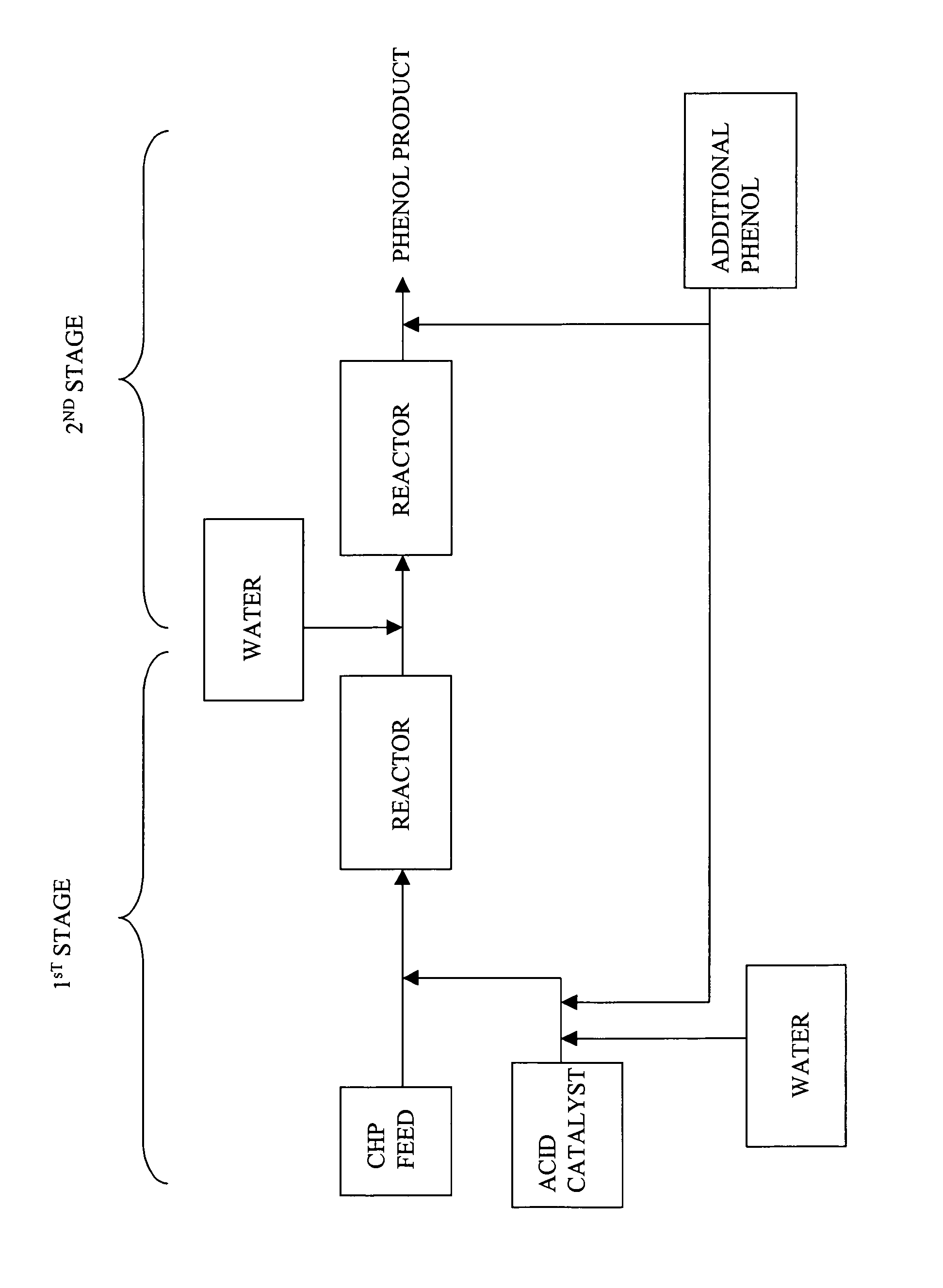
Process for producing phenol

a technology of phenol and acetone, which is applied in the field of producing a phenol stream, can solve the problems of reducing the quality of phenol products, reducing the efficiency of phenol production,

Inactive Publication Date: 2006-09-19
SABIC GLOBAL TECH BV
View PDF49 Cites 26 Cited by
  • Summary
  • Abstract
  • Description
  • Claims
  • Application Information

AI Technical Summary

Benefits of technology

[0014]The present disclosure may be understood more readily by reference to the following detailed description of the various features of the disclosure and the examples included therein.

Problems solved by technology

Although extra acetone addition can be an effective method for inhibiting the CHP decomposition reaction and enhancing DCP formation, such a cleavage process operating with a high acetone:phenol ratio is subject to the disadvantage of forming increased levels of other harmful “carbonyl-type” by-products such as hydroxyacetone (also known as HA or acetol) and mesityl oxide (MO).
Moreover, as a result of the carbonyl impurities formed during cleavage, the resulting phenol and acetone products have to be separated from these undesirable by-products and impurities using energy intensive processes.
For example, the presence of acetol impurities in the phenol product renders quality unacceptable for many end-use applications, such as in the production of bisphenol-A, diphenyl carbonate, and polycarbonate.
Furthermore, the phenol product that contains acetol impurities tends to discolor upon aging, or during subsequent reactions, such as during sulfonation and chlorination reactions.
The hydroxyacetone impurity has proven to be particularly difficult to remove from the phenol product in a downstream process since it co-distills at a similar temperature as phenol during thermal separation processes, e.g., rectification processes.
Because of this, current thermal separation processes are generally ineffective at purifying the phenol product to remove the acetol impurity.
All of these approaches are costly, requiring expensive reagents and additional equipment.

Method used


Image

  • Process for producing phenol

Examples


examples

[0036]In these Examples, the analysis of hydroxyacetone was carried out on an Agilent 6890 Gas chromatograph (GC). GC separation was carried out on glass column with a length 24 inches &¼ inch outer diameter, configured for on column injection, packed with chromsorb 102 80 / 100 mesh, with helium as carrier gas at 30 milliliters per minute (ml / min). The injector temperature was maintained at 160° C. and the detector temperature was maintained at 250° C. The initial column temperature was kept at 110° C. for 3 minutes hold time, this was followed by a temperature increase at 7° C. per minute to reach 150° C., held for 2 minutes, at 150° C., followed by a temperature increase at 10° C. per minute to reach 200° C. and held at 200° C. for 15 minutes. The column was calibrated with standard hydroxyacetone (obtained from Aldrich Chemical Company, 97% pure) at a concentration ranging from 5 parts per million (ppm) to 244 ppm made in a 50:50 mixture of cumene and phenol. Hydroxyacetone in the...

examples 1 – 3

Examples 1–3

[0043]In these examples, CHP was decomposed in a continuous 2-STEP process to obtain a phenol product, wherein the molar ratio of phenol to acetone was greater than or equal to 1.2:1, and the effluent produced from the first step contained at least 1% residual CHP. Table 3 illustrates the composition of the feed stream. The process generally included adding CHP to an agitated mixture of phenol, acetone, and sulfuric acid.

[0044]In the first step of the continuous process, a typical synthetic feed composition having phenol, acetone, and CHP was fed to a glass reactor fitted with a condenser having a capacity of about 150 milliliters through the respective inlets for the feed stream and acid catalyst. The reactor was also fitted with a temperature probe to monitor the temperature and external heating / cooling jacket to maintain the temperature. The contents of the reactor were continuously stirred with a magnetic stirrer. The composition of the feed stream and amount of cata...


PUM

PropertyMeasurementUnit
temperatureaaaaaaaaaa
weight percentaaaaaaaaaa

Abstract

A process for producing a phenol product generally comprises a first step comprising reacting in a first reactor a feed stream comprising cumene hydroperoxide and water with an acid catalyst to produce an effluent comprising the phenol product, acetone, and at least 1% by weight residual cumene hydroperoxide, and a second step comprising passing the effluent into a second reactor and decomposing the residual cumene hydroperoxide, wherein during said process the ratio of phenol to acetone is maintained at a molar ratio of greater than 1:1, and wherein the water in each of the first and second steps is present in an amount more than 0 and less than or equal to 5 weight percent based on the total weight of the feed stream or effluent, and wherein the process is continuous.

Description

CROSS REFERENCE TO RELATED APPLICATIONS[0001]The present application is a continuation-in-part application of and claims priority to, U.S. patent application Ser. No. 10 / 815,575 filed on Mar. 31, 2004, now abandoned, incorporated herein by reference in its entiretyBACKGROUND[0002]The present disclosure generally relates to a method for producing a phenol stream with reduced by-products. More particularly the present invention relates to a two-step continuous method for producing a phenol stream with reduced by-products.[0003]The cleavage reaction of cumene hydroperoxide (CHP) in the manufacture of phenol and acetone from cumene is well known. Today most modern CHP cleavage processes are carried out in a continuous flow manner and utilize the so-called “2-stage cleavage process”, which provides the best economics because, in addition to making phenol and acetone from CHP, it recovers cumene value from the by-product DMBA formed in the prior cumene oxidation step. Such prior art 2-sta...

Claims


Application Information

Patent Timeline
Patent Type & Authority Patents(United States)
IPC IPC(8): C07C37/08C07C39/04
CPCC07C37/08C07C39/04
Inventor TATAKE, PRASHANT ANILKUMBHAR, PRAMOD SHANKARSINGH, BHARATFULMER, JOHN WILLIAMMANDAL, SABYASACHIKUMAR, ARUN N.PAWAR, RUPESH
Owner SABIC GLOBAL TECH BV
Why Eureka
Try Eureka