Subsampling RF receiver architecture

a receiver and subsampling technology, applied in the field of subsampling rf receiver architecture and receiver circuitry, can solve the problems of increasing wireless traffic, affecting the availability of communications bandwidth, and inability to integrate saw filters with conventional semiconductor integrated circuits, so as to reduce manufacturing costs and power dissipation, and provide high performance.

Inactive Publication Date: 2006-09-19
TEXAS INSTR INC
View PDF10 Cites 47 Cited by
  • Summary
  • Abstract
  • Description
  • Claims
  • Application Information

AI Technical Summary

Benefits of technology

[0016]It is therefore an object of this invention to provide a radio frequency (RF) receiver that provides high performance at a reduced manufacturing cost and power dissipation.
[0018]It is a further object of this invention to provide such a receiver in which analog mixers need not be used or reduced in complexity.
[0019]It is a further object of this invention to provide such a receiver in which power consumption is also minimized.

Problems solved by technology

This increasing wireless traffic strains the available communications bandwidth for a given level of system infrastructure.
As a result, relatively costly and complex techniques are commonplace in these systems.
However, because of the piezoelectric substrate, SAW filters are not integratable with conventional semiconductor integrated circuits.
Accordingly, the use of SAW filters adds significantly to system cost.
However, this conventional heterodyne architecture is quite costly to implement, and also consumes a great deal of power, which is problematic for battery-powered devices such as wireless telephone handsets.
The multiple downconversions necessary to bring the input signal to baseband exacerbate these issues.
While this architecture reduces the cost of manufacture relative to the heterodyne architecture of FIG. 1, the use of only one level mixer for downconversion causes this architecture to suffer from DC offset problems, significant even-order distortion, and flicker noise.
However, two SAW filters are still required in digital mixer receiver 30, maintaining relatively high cost for this approach.

Method used


Image

  • Subsampling RF receiver architecture
  • Subsampling RF receiver architecture
  • Subsampling RF receiver architecture

Examples


first embodiment

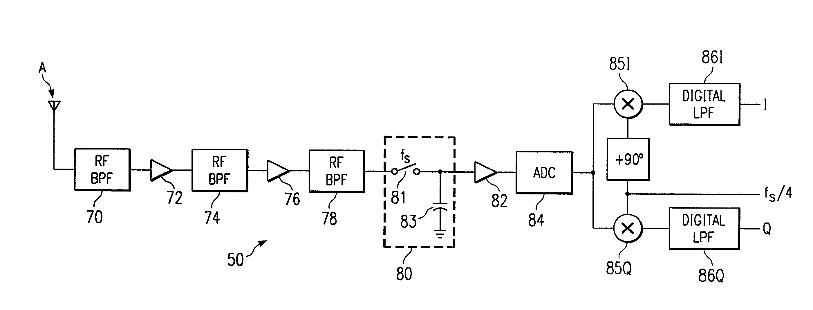
[0045]Referring now to FIG. 6, the construction and operation of subsampling receiver 50 according to this invention will now be described in detail. As will be apparent from the following description, subsampling receiver 50 is constructed so as to be efficiently buildable into a single integrated circuit, along with other analog functions contained within wireless handset 30, if desired. As shown in FIG. 6, the signal from antenna A is received by subsampling receiver 50. FIG. 5c illustrates the frequency spectrum of this signal, including both the RF input signal RFI, which is centered at a high, RF, frequency, and also broadband noise NRFI. This signal is applied to first RF bandpass filter 70, which filters the received signal to the frequency range around its carrier frequencies. According to this embodiment of the invention, after bandpass filter 70, the filtered signal is applied to low-noise amplifier (LNA) 72, which amplifies the signal by on the order of 20 dB with a nois...

second embodiment

[0055]Referring now to FIG. 7, the construction and operation of subsampling receiver 50′ according to a second preferred embodiment of the invention will now be described in detail. According to this second embodiment of the invention, each of the in-phase and quadrature components I, Q have their own sample-and-hold circuits, and as such avoids the necessity for digital mixers. In addition, as will become apparent from this description, subsampling receiver 50′ is particularly well-suited for use in a multi-mode WCDMA receiver.

[0056]Antenna A is connected to duplexer 88, as shown in FIG. 7; as known in the art, duplexer 88 is a conventional circuit that combines both the transmit and receive signals over antenna A. Duplexer 88 attenuates the received signal from antenna A by on the order of 3 dB, as is typical. In this embodiment of the invention, signals received from antenna A via duplexer 88 are amplified by LNA 90, having a gain of on the order of 20 dB and a noise figure of 2...


PUM


Abstract

A subsampling receiver (50, 50′, 50″) for converting an RF signal to baseband is disclosed. The subsampling receiver (50, 50′, 50″) may be implemented into a wireless communications device (40), such as a wireless telephone handset. In one disclosed embodiment, the receiver (50) includes a sample and hold circuit (80) that samples a bandpass filtered input modulated signal at the subsampling frequency (fs) that is well below the RF carrier frequency but twice the bandwidth (BW) of the payload; the sampled signal is digitized, and applied to two digital mixers (85I, 85Q) to produce in-phase and quadrature components (I,Q) of the payload. In another embodiment, the receiver (50′) includes two sample and hold circuits (96I, 96Q) to sample the filtered signal at different phases of the sampling frequency, to produce the in-phase and quadrature digital components. In a third embodiment, the receiver (50″) includes an analog mixer (116) to downconvert the RF input to an intermediate frequency, prior to digitization and digital mixing at quadrature phase.

Description

CROSS-REFERENCE TO RELATED APPLICATIONS[0001]This application claims priority, under 35 U.S.C. §119(e), of Provisional Application No. 60 / 282,582, filed Apr. 9, 2001.STATEMENT REGARDING FEDERALLY SPONSORED RESEARCH OR DEVELOPMENT[0002]Not applicable.BACKGROUND OF THE INVENTION[0003]This invention is in the field of wireless communications, and is more specifically directed to receiver circuitry used in such communications.[0004]The popularity of mobile wireless communications has increased dramatically over recent years. It is expected that this technology will become even more popular in the foreseeable future, both in modern urban settings, and also in rural or developing regions that are not well served by line-based telephone systems. This increasing wireless traffic strains the available communications bandwidth for a given level of system infrastructure. As a result, there is substantial interest in increasing bandwidth utilization of wireless communications system to handle t...

Claims


Application Information

Patent Timeline
Patent Type & Authority Patents(United States)
IPC IPC(8): H04B1/26H04B15/00H04B1/28H04B1/30
CPCH04B1/0003H04B1/28H04B1/0025H04B1/30
Inventor MOSTAFA, MOHAMED A. I.EMBABI, SHERIFFERNANDO, MODERAGE C.CHAN, WING KANGORE, JR., CHARLES
Owner TEXAS INSTR INC
Why Eureka
Try Eureka