In-tube ultrasonic device for wall thickness metering

a technology of ultrasonic devices and wall thickness meters, which is applied in ultrasonic/sonic/infrasonic diagnostics, instruments, diagnostic recording/meauring, etc. it can solve the problems of limited space, increased data volume per given length of pipeline, and difficult to interpret data loss, so as to increase the accuracy of measurements and increase the control distance. , the effect of increasing the speed of hardware data processing

Inactive Publication Date: 2006-09-26
WEATHERFORD TECH HLDG LLC +1
View PDF18 Cites 47 Cited by
  • Summary
  • Abstract
  • Description
  • Claims
  • Application Information

AI Technical Summary

Benefits of technology

[0020]The basic technical task obtained as a result of realization of the invention is reduction of the storage elements necessary for the flaw detection of the pipeline of a given length (therefore, an increase of the distance controlled per pass of the inspection pig with a given volume of the data) and an increase of the accuracy of measurements and of the speed of the hardware data processing.
[0021]The mechanism of attaining said technical results consists in that the direct digital m

Problems solved by technology

The measurements with an accuracy sufficient for detection and identification of the flaws and for determination of their parameters requires the use of large-capacity storage devices, whereas the pig moving inside the pipeline has a limited space for data storage devices.
However, the absence of data on the greater part of the length of the monitored pipeline makes it difficult to interpret the data loss

Method used


Image

  • In-tube ultrasonic device for wall thickness metering
  • In-tube ultrasonic device for wall thickness metering
  • In-tube ultrasonic device for wall thickness metering

Examples


Embodiment Construction

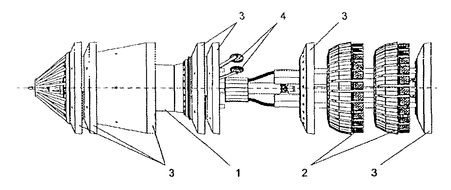
[0057]The improvement of the ultrasonic inspection pigs (flaw detectors) allows an increase in the distance monitored per diagnostic pass and an increase in the data processing rate. As a result, an in-tube ultrasonic inspection pig (flaw detector) that can be used for inspection of pipelines with a nominal diameter from 10″ up to 56″ is provided.

[0058]The inspection pigs in preferable embodiments occupy about 85% of the nominal diameter of the pipeline and minimum passable turning radius of about 1.5 times the pipeline diameter. The inspection pigs operate at a pumped medium temperature of 0° C. to +50° C. and withstand the medium pressure of up to 80 atmospheres. The inspection pigs have explosion protection such as > and > at an input electric current not exceeding 9 A.

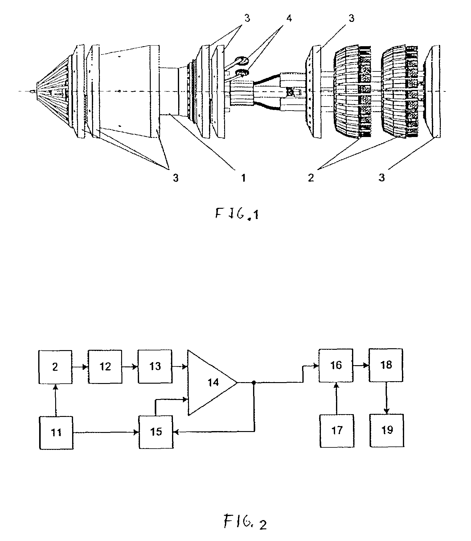
[0059]The in-tube ultrasonic flaw detector for inspection of a pipeline having a diameter of 38″ to 56″ and a wall thickness of 4 to 23.5 mm in one preferable design embodiment shown in FIG. 1 includes: a housing 1...


PUM


Abstract

What is claimed is an inspection device for in-tube monitoring of main pipelines by the method of ultrasonic wall thickness metering realized in a device traveling inside the pipeline and performing measurements, acquisition of measurement data and their interpretation. The device comprises a probing pulse generator, an ultrasonic transducer, an amplifier, a comparator with an analog input, a digital timer, a processor and a data storage module, and a controlled reference voltage source connected in series. The output of said reference voltage source is connected to the reference voltage input of the comparator, said reference voltage source being capable of setting at least two different voltages at its output.
The comparator output is connected to one of the control inputs of the reference voltage source that allows one to switch threshold values in the comparator, when recording the ultrasonic pulses, to use one threshold value to record the moment of reception of the ultrasonic pulse reflected from the internal wall of the pipeline using another threshold value of the comparator to record the moment of reception of the ultrasonic pulse reflected from the external wall of the pipeline using the other threshold value. Thus, the operator can perform direct measurements of the transit time of the ultrasonic pulses in the pipe wall allowing him to increase the distance monitored per one pass of the device, and to increase the accuracy of measurements and the rate of hardware data processing compared to the prototypes known in the art.

Description

BACKGROUND OF THE INVENTION[0001]The present invention relates to devices for flaw detection of long-distance pipelines, mainly trunk oil pipelines, oil-products pipelines and gas pipelines, by providing acoustic coupling between the ultrasonic transducers and the pipe walls (for example, with the help a fluid plug) and using the method of thickness metering and a so-called “pig” or a scanning device which is put into the pipeline and transported under power of the fluid flow in the pipeline. The scanning pig has built-in transducers, means for measurement, conversion and recording of the measured data and a device for collecting the digital data in the process of pig travel and for processing the obtained data to detect the flaws in the pipe walls and to determine the parameters of the detected flaws, as well as their location in the pipeline.[0002]Known in the art is a device for in-tube flaw detection [RU2018817, RU2042946, RU2108569, U.S. Pat. No. 4,162,635], comprising a body w...

Claims


Application Information

Patent Timeline
IPC IPC(8): G01N29/04G01B17/02G01N29/265G01N29/44
CPCG01B17/02G01N29/265G01N29/4427G01N2291/2636G01N2291/02854
Inventor BAZAROV, ALEXANDR J.DESYATCHIKOV, ALEXANDR P.KARASEV, NIKOLAI A.KIRICHENKO, SERGEI P.SLEPOV, ANDREI M.SMIRNOV, ANATOLY V.HRAPOV, SERGEI N.
Owner WEATHERFORD TECH HLDG LLC
Why Eureka
Try Eureka