Parallel semi-continuous or continuous reactor system

a semi-continuous or continuous reactor technology, applied in the direction of liquid gas reaction of thin film type, gas-gas reaction process, instruments, etc., can solve the problems of slow and arduous process of chemical synthesis, and achieve the effect of preventing undesired mixing of contents, reducing volume, and gradually increasing system pressur

Inactive Publication Date: 2006-10-03
FREESLATE
View PDF37 Cites 21 Cited by
  • Summary
  • Abstract
  • Description
  • Claims
  • Application Information

AI Technical Summary

Benefits of technology

[0011]In a much more specific embodiment, a 96-cell semi-continuous parallel reactor block is provided. Ideally, each vessel may be located at standard microtiter plate spacing. A separate header barrel is used for each reactor vessel and 96 header barrels are disposed in a header block. The reactor vessels within the reactor block are disposable glass vials, and the header barrels within the header block are glass syringes. The blocks and hence the reactor vessels are connected together with an inert orifice, which is the transfer line and also serves to thermally insulate the vessel from the barrel, as well as prevent undesired mixing of the contents of the two vessels. In this specific embodiment, the reactor vessel is constant volume, initially filled only partially with liquid, leaving a compressible gas headspace in the vessel. The header barrel's volume is decreased throughout the reaction as the contents of the header are injected into the reactor, causing the pressure of the system gradually increase. Additional pressure rise is caused as the reactor vessels are heated, potentially above the boiling point of the liquids inside. Filling and assembly of the reactor / header reaction system may done in two halves, first by filling the reactor vessels to a desired amount and then filling the header barrels to a desired amount. The tops of the reactor vessels and header barrels are held in an array format by a collar, which leaves a portion of the bottom of each reactor vessel exposed. The reactor vessels are filled with different mixtures via a fluid-handling robot or manually. The collar is used to move all reactor vessels from a filling station into the reactor block at once. This allows the filling station to be independent of the reactor block, and also allows automated robotic handling and transfer of the reactors from one station to another. The header barrels are open at the end opposite the plunger rod. This allows the headers to be filled by direct dispensing (manual or automated), rather than by aspiration from another container. This ensures that the header vessel mixture is not altered in the event that the mixture is non-homogeneous. This open-end design also allows addition of mixing balls into the header, and reduces entrapment of gasses. Once the headers are filled, a plate containing individual orifices at each vessel position seals the entire array at once. The header barrels may be inverted and attached onto the reactor vessels. The orifices keep the header contents from spilling during the inversion, and are sized to keep the fluid velocity during injection much higher than the diffusion rate, keeping the contents of the header vessel separated from the reactor vessels during a reaction.

Problems solved by technology

However, compared to HTS protocols, chemical synthesis has historically been a slow, arduous process.

Method used


Image

  • Parallel semi-continuous or continuous reactor system
  • Parallel semi-continuous or continuous reactor system
  • Parallel semi-continuous or continuous reactor system

Examples


Embodiment Construction

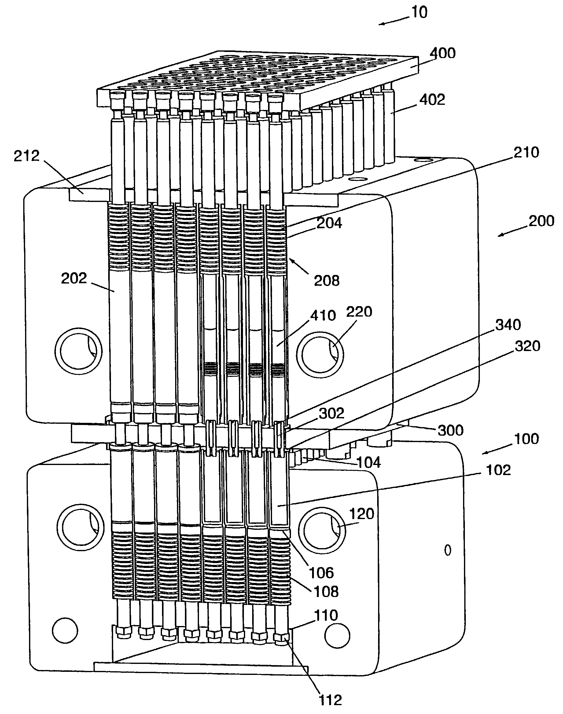
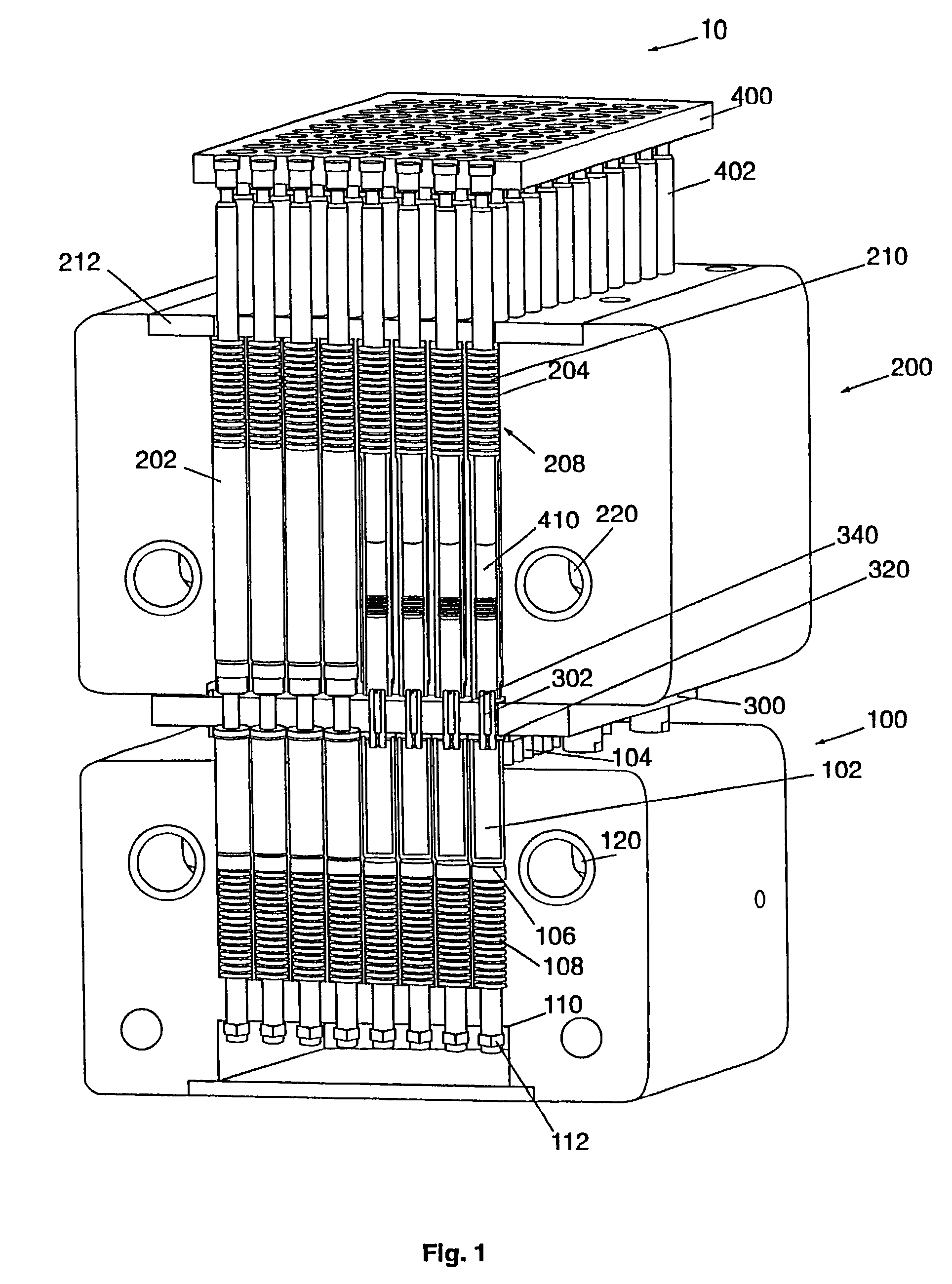
[0039]The present invention provides an apparatus and method for carrying out multiple reactions in parallel. It is especially useful for synthesizing and / or screening combinatorial libraries. The term “header barrel” is used to describe the container that holds the one or more reactants that are fed into the reactor from the sources in the header. The term “barrel” is not intended to be limiting and a header barrel can take any convenient form including a vessel, tank, barrel, pipe, vial, syringe or other form of container. Also, the phrase “storage tank” is used to describe the container that holds the material that exits the reactor. The term “tank” is not intended to be limiting and a storage tank can take any convenient form including a vessel, tank, barrel, pipe, vial, syringe or other form of container.

[0040]FIG. 1 shows a constant volume embodiment of a parallel reactor system 10. The system 10 comprises a reactor block 100 and a header block 200 having sandwiched between th...


PUM

PropertyMeasurementUnit
timeaaaaaaaaaa
timeaaaaaaaaaa
feed timeaaaaaaaaaa

Abstract

A method and apparatus for reacting a plurality of different mixtures in parallel in a semi-batch or continuous mode is provided. Each reaction is contained within a reactor vessel, the reactor vessels combined into a reactor block. Reactant(s) to be added during the reaction are kept in a header barrel, which has a plunger to feed reactant(s) from the header barrel through a transfer line into the reactor vessel. The plunger is moved using a drive system. The header barrels are optionally combined in a header block. The header block is sealed to a plate containing the transfer lines, which in turn is sealed to the reactor block. A latch mechanism is provided for easy sealing of the reactor and header blocks to the plate. The entire apparatus may be placed on a rocker or rotating plate for mixture as the reaction is proceeding.

Description

[0001]This application is a continuation of U.S. Ser. No. 09 / 755,388, filed Jan. 4, 2001 now U.S. Pat. No. 6,566,461, which is a divisional of U.S. Ser. No. 09 / 205,071 filed Dec. 4, 1998 and issued as U.S. Pat. No. 6,485,692, both of which are incorporated herein by reference, the teachings of which are incorporated herein by reference.BACKGROUND[0002]1. Technical Field[0003]The present invention relates to a method and apparatus for rapidly making, screening, and characterizing an array of materials in which process conditions are controlled and monitored, and in particular where the feed to each reactor vessel is continuously fed.[0004]2. Discussion[0005]Combinatorial materials science generally refers to methods for creating a collection of diverse compounds or materials using a relatively small set of precursors and / or methods for rapidly testing or screening the collection of compounds or materials for desirable performance characteristics and properties. As currently practiced...

Claims


Application Information

Patent Timeline
Patent Type & Authority Patents(United States)
IPC IPC(8): B01J19/00G01N35/02B01J4/00B01J19/26C08F2/00C40B40/14C40B60/14G01N35/10
CPCB01J19/0046Y10T436/11B01J2219/00308B01J2219/0031B01J2219/00313B01J2219/00315B01J2219/00319B01J2219/00351B01J2219/00481B01J2219/00484B01J2219/00495B01J2219/00585B01J2219/00691B01J2219/0072B01J2219/00722C40B40/14C40B60/14Y10S526/92Y10T436/25625Y10T436/2575Y10T436/25B01J2219/0029
Inventor FREITAG, J. CHRISTOPHERHAJDUK, DAMIANNIELSEN, RALPH B.SAFIR, ADAMTIEDE, RICHARD
Owner FREESLATE
Why Eureka
Try Eureka