
System for axial pattern analysis of multicellular organisms

a multicellular organism and axial pattern technology, applied in the field of automatic analysis of complex multicellular model organisms, can solve the problems of inability to accurately assess the effect of one or more compounds on the development or physiology of multicellular organisms, inability to achieve high-speed, high-throughput drug discovery, and inability to achieve high-throughput drug discovery

Inactive Publication Date: 2006-10-03
UNION BIOMETRICA
View PDF22 Cites 47 Cited by
  • Summary
  • Abstract
  • Description
  • Claims
  • Application Information

AI Technical Summary

Benefits of technology

[0013]The present invention provides a system for identifying and physically selecting multicellular organisms from mixed populations on the basis of spatially distinct, optically detectable, phenotypic characteristics. Two key components of this system include the use of fluorescence markers to provide positional and orientational information about model multicellular organisms. According to certain aspects of the invention, strains of model multicellular organisms are generated that have a first marker pattern feature that is spatially consistent and is used to orient the organisms along their major axes. In preferred embodiments, the strains of model organisms also include a second inducible

Problems solved by technology

However, such automated drug screening assays are not readily available for assessing the in vivo effects of multiple compounds on complex multicellular organisms.
In particular, assessing the effect of one or more compounds on the development or physiology of a multicellular organism remains a tedious manual task requiring hundreds of hours of labor by highly skilled technicians.
While model organisms such as C. elegans, D. melanogaster, and D. rerio have been proven useful in the study of human disease, they have not yet been successfully used in the field of high speed, high throughput drug discovery.
This presents a significant hindrance to investigators that need to search through thousands of multicellular organisms for the phenotype of a new mutation or for a response to a panel of sample drugs.
The use of such slow, manual methods for the selection and deposition of organisms of the proper type greatly delays the entire process of drug discovery.
Moreover, manual methods rely on pipettes that dispense accurate volumes of fluid but not accurate numbers of organisms.
Like the selection and deposition step, this is an extremely tedious task requiring a significant number of workers that are trained at high academic levels.
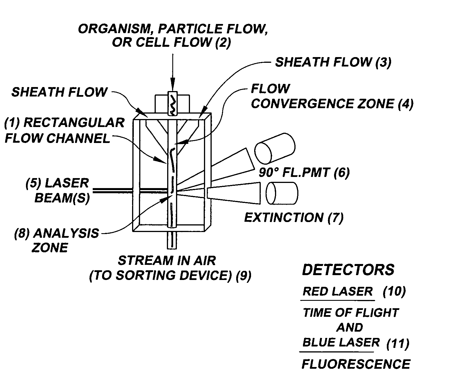
This narrow line of focus is sufficient for analyzing single cells, but is insufficient for detecting and spatially locating a particular feature against the more complex background profile of light scatter and autofluorescence presented by a multicellular organism.
In the case of D. melanogaster (fruit fly) larvae, the situation is even worse because the diameter of an advanced stage larva is of the order of one millimeter, which means that autofluorescence is much more than a hundred times greater than in single blood cells.
The use of the impedance sensor, which can only estimate overall size, and cannot spatially resolve localized features along the major axis of the organism limits the Byerly et al. instrument.
In addition to this limitation, the Byerly et al. instrument could not select and deposit (sort) specific organisms.
However, this instrument reports only the intensity, not the position of fluorescence along the major (long) axis of the organisms.

Method used


Image

  • System for axial pattern analysis of multicellular organisms
  • System for axial pattern analysis of multicellular organisms
  • System for axial pattern analysis of multicellular organisms

Examples


example 1

Simultaneous NACLS and Fluorescence From C. elegans

[0103]A light scatter sensor was placed at various angular positions with respect to the optical axis in the forward scatter direction. The collection cone angle was approximately six degrees (NACLS). A photomultiplier with a 20×-collection lens and a barrier filter optimized for fluorescence from GFP was used on the fluorescence detector. The C. elegans that were used for this illustration expressed GFP at two locations in the “head” and nowhere else. The oscilloscope traces for light scatter and fluorescence are shown in FIGS. 4 and 5.

[0104]The traces show the passage of the organism through the line focus laser beam. The lower trace (1) is the light scatter signal and the top trace (2) is the fluorescence signal. The x-axis is time. FIG. 4 is typical of a class of light scatter traces observed with a NACLS detector. The detector was placed at a 45 degree forward light scatter angle directly below the laser beam axis (below the h...

example 2

Problems Associated with Optical Extinction Signals as Trigger and Timing Signals

[0106]FIG. 6 illustrates another problem associated with improper placement of a light scatter detector for triggering. In this case a sensor was place directly on axis and in the laser beam. The object was to measure light blockage (extinction) by the organisms. Light extinction is a possible alternative to the preferred WACLS (light scatter) trigger of the present invention. The test C. elegans had a single weak region of fluorescence at a neuronal location in the head located slightly posterior to the tip of the “nose.” A 40×objective was used to collect more light since this organism was very weakly fluorescent. The extinction sensor collected light over a two degree cone. In this case, the extinction trace returns to baseline during the passage of the nematode, and even becomes slightly negative. Therefore, this signal could not be used as a trigger or timing signal.

example 3

Simultaneous WACLS and Fluorescence from C. elegans

[0107]A photodetector was placed on the optic axis with a collection cone angle of approximately 30 degrees (WACLS). A mask was placed over the center front of the detector to block any directly transmitted light or stray scattered light from the flow cell capillary. This way, the detector collected light scatter from the organisms over a several times wider cone angle than in the previous examples. The photomultiplier with a 40×collection lens and a barrier filter for green fluorescence protein was used to detect fluorescence since the fluorescence signal was very weak.

[0108]FIG. 7 shows a WACLS signal on the lower trace and the associated fluorescence signal on the upper trace. Note that the WACLS signal begins and ends at the proper time and does not return to baseline during the passage of the nematode. This was a consistent and systematic observation so long as the acceptance angle was sufficiently wide and light from the illu...


PUM

PropertyMeasurementUnit
Timeaaaaaaaaaa
Angleaaaaaaaaaa
Angleaaaaaaaaaa

Abstract

A method of using elongate multicellular organisms in conjunction with a specialized flow cytometer for drug discovery and compound screening. A stable, optically detectable linear marker pattern on each organism is used to construct a longitudinal map of each organism as it passes through the analysis region of the flow cytometer. This pattern is used to limit complex data analysis to particular regions of each organism thereby simplifying and speeding analysis. The longitudinal marker pattern can be used to alter signal detection modes at known regions of the organism to enhance sensitivity and overall detection effectiveness. A repeating pattern can also be used to add a synchronous element to data analysis. The marker patterns are established using known methods of molecular biology to express various indicator molecules. Inherent features of the organism can be rendered detectable to serve as marker patterns.

Description

PRIORITY INFORMATION[0001]This application is a continuation-in-part of U.S. application Ser. No. 09 / 932,413, filed Aug. 17, 2001 now abandoned, which claims priority to U.S. Provisional Application No. 60 / 226,701, filed Aug. 18, 2000. This application is also a continuation in part of U.S. application Ser. No. 09 / 465,215, filed Dec. 15, 1999 now abandoned, which claims priority to U.S. Provisional Application No. 60 / 112,280, filed Dec. 15, 1998. Each of the above-referenced applications is incorporated herein by reference.FIELD OF THE INVENTION[0002]This invention concerns the field of automated analysis of complex, multicellular model organisms that are particularly useful in the field of drug discovery, of toxicology, and development.BACKGROUND OF THE INVENTION[0003]Rapid, high-throughput compound screening assays have revolutionized the field of drug discovery. Automated drug discovery assays measure changes in a variety of biochemical pathways in vitro. For example, microarray ...

Claims


Application Information

Patent Timeline
IPC IPC(8): G01N21/00B07C5/36G01N33/553G01N15/02G01N15/14G01N33/50
CPCG01N15/147G01N15/1475G01N33/5085G01N15/1427G01N15/1429G01N2015/145G01N2015/1477G01N2015/149G01N2015/1497G01N15/1433G01N15/149
Inventor HANSEN, W. PETERFERRANTE, ANTHONY A.GERSHMAN, RUSSELL J.KRAULEDAT, PETRA B.PERRAULT, JR., DONALD F.
Owner UNION BIOMETRICA
Learn More