
Covered stent assembly for reduced-shortening during stent expansion

a stent and stent technology, applied in the field of expandable endoprosthesis devices, can solve the problems of affecting the stent's expansion rate, the inability to fully rest, and the potential for atherosclerotic plaque particles, so as to speed up the endothelialization process, minimize the shrinkage of the stent, and minimize the shortening of the stent

Inactive Publication Date: 2006-10-10
ABBOTT CARDIOVASCULAR
View PDF20 Cites 53 Cited by
  • Summary
  • Abstract
  • Description
  • Claims
  • Application Information

AI Technical Summary

Benefits of technology

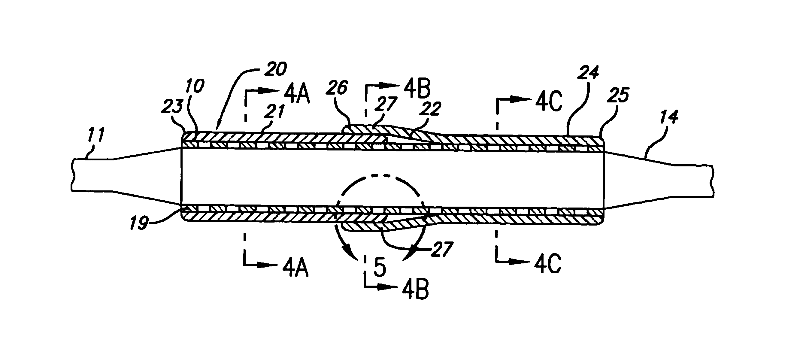
[0013]The present invention is directed to covered stents for implantation in body vessels which will hold up occluded, weakened or damaged portion of the vessels. The present invention provides a covering made from a polymeric material to cover the gaps formed between stent struts in order to minimize embolic events as well as plaque prolapse that can occur between the struts, especially when the device is placed in regions where the plaque is characterized by a friable, grumous-like nature. The present invention provides a composite intraluminal device which includes a tubular shaped stent having distal and proximal ends, along with internal and external surfaces which extend along a longitudinal stent axis. A tubular covering of polymeric material having open distal and proximal ends can be affixed to the underlying stent and can expand with the stent when placed within a body lumen. Because the device is a covered stent and sometimes covered stents shorten more than bare stents, the tubular covering has an overlap portion that shortens when the stent is expanded in order to minimize covered stent shortening.
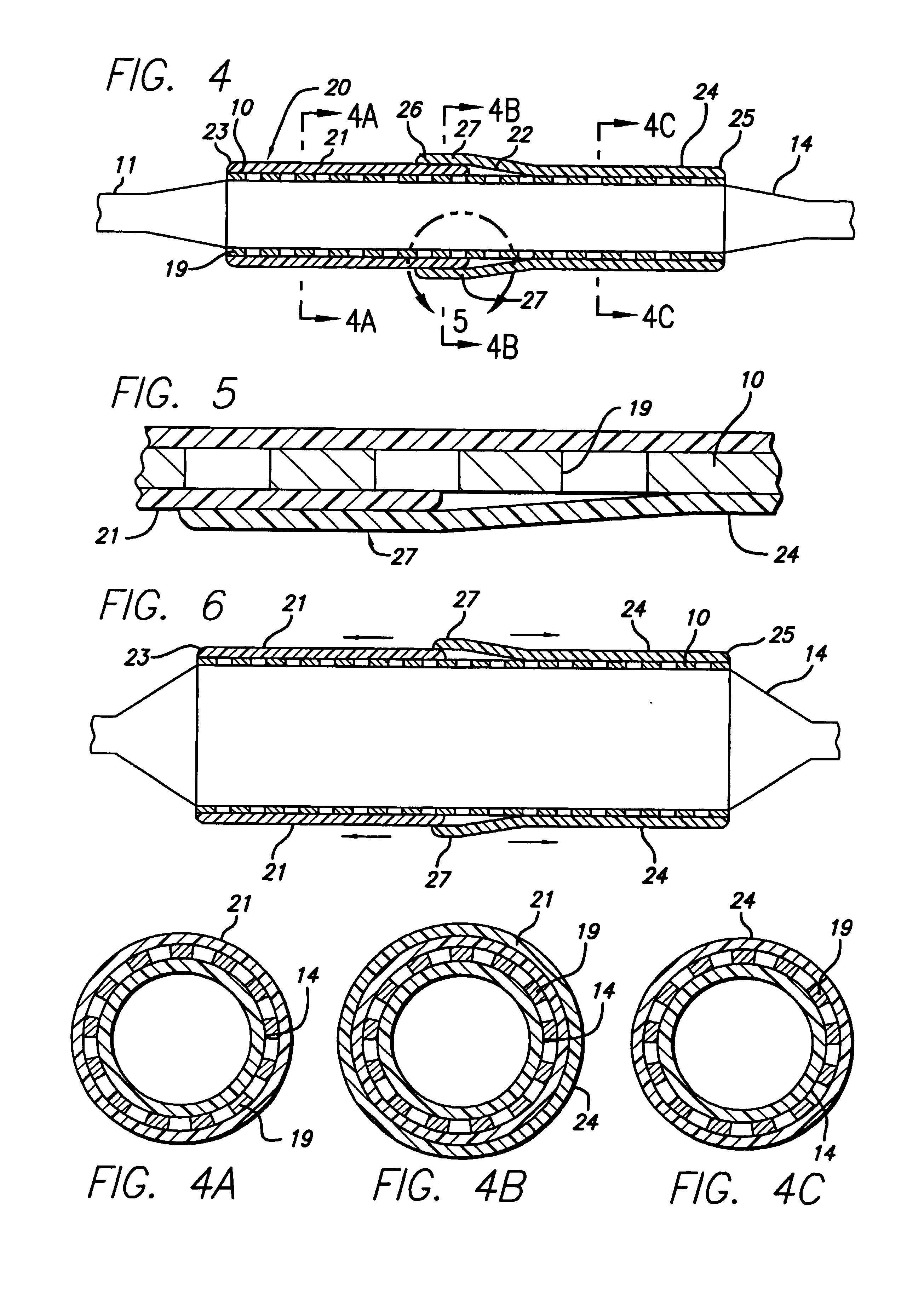
[0014]In one embodiment of the present invention, the stent covering is made from two segments of a tubular material which are affixed to the underlying stent by bonding one end of the one of the segments to the stent, and bonding one end of the second segment to the other end of the stent using bonding materials such as solvents or adhesives. The placement of the bonding material only at the ends of the first and second sections allows the stent sections to fully expand radially without interference from the cover material which will expand with the stent, and which allows the stent to maintain it continuous tubular opening once deployed in the body vessel. The length of each segment is such that they are shorter than the overall length of the stent so that they form an overlapping portion between the distal and proximal ends of the stent. As the stent expands, the overlapping portion of the first segment slides over the overlapping portion of the second segment shortening the overlap portion and thereby minimizing any shrinkage effect that a fully-constrained cover would have on the stent. The tubular coverings preferably are made from seamless tubing of a material which is less susceptible of breaking compared to prior art covered stents. As a result, an intraluminal device made in accordance with the present invention has sufficient structural strength and reduced strain on the stent struts, and is therefore less prone to failure.
[0015]In another embodiment of the present invention, the stent covering is made from a single segment oftubular material which is affixed to the underlying stent by bonding the ends of the tubular covering to the stent using bonding materials such as solvents or adhesives. The placement of bonding material only at the ends of the tubular covering allows the covering to fully expand radially without deforming which allows the stent to maintain its continuous tubular opening once deployed in the body vessel. An overlap portion is formed in the cover material between its distal and proximal ends by folding the material to form three layers. As the stent expands, the overlapping layers slide over each other and thus minimize any shrinking effect the cover has on the stent. The tubular covering preferably is made from a seamless tubing of material which is less susceptible of breaking, compared to prior art covered stents which use adhesive to create a seam on the covering. As a result, an intraluminal device made in accordance with the present invention, has sufficient material strength once expanded in the deployed position and results in an expanded stent having circular openings which maintain a normal pattern of blood flow through the area of treatment.

Problems solved by technology

However, a danger which is always present during these procedures is the potential for particles of the atherosclerotic plaque, which can be extremely friable, breaking away from the arterial wall.
Debris that is carried by the bloodstream to distal vessels of the brain can cause these cerebral vessels to occlude, possibly resulting in a stroke.
Therefore, although cerebral percutaneous transluminal angioplasty has been performed in the past, the number of procedures performed has been limited due to the fear of causing an embolic stroke should embolic debris enter the bloodstream and block vital downstream blood passages.
For example, excessive cell or tissue growth (intimal hyperplasia) can cause partial restenosis to develop over time, which is detrimental to the patient.
The tissue or cell growth can extend into the tubular opening created by the stent and can block or otherwise re-occlude the opening and can possibly cause abnormal blood flow through the stent which can cause formation of thrombi that are detrimental to the patient's health.
Some prior art covered stents are difficult to manufacture due to the flexibility of the covering and the requirement that the covering be capable of expansion when the stent is deployed within the patient's vasculature.
A covering which does not expand normally can cause the stent to misalign within the body vessel and can cause an non-uniform deployment of the stent.
Such coverings can be more susceptible to tearing, especially at the seam, when the stent is expanded.
Some prior art stents that are covered may have a tendency to shorten when expanded and the covered material also shortens, providing an undesirable result.
As the stent and the covered material are expanded into contact with an artery or vessel wall, the shortening movement may scrape along the artery wall and cause injury or dislodge plaque material which may embolize.
Further, as these prior art covered stents shorten upon expansion, the cover material shortens past the stent struts at the stent ends, leaving a covered stent with exposed stent struts, and not fully covered upon expansion.

Method used


Image

  • Covered stent assembly for reduced-shortening during stent expansion
  • Covered stent assembly for reduced-shortening during stent expansion
  • Covered stent assembly for reduced-shortening during stent expansion

Examples


Embodiment Construction

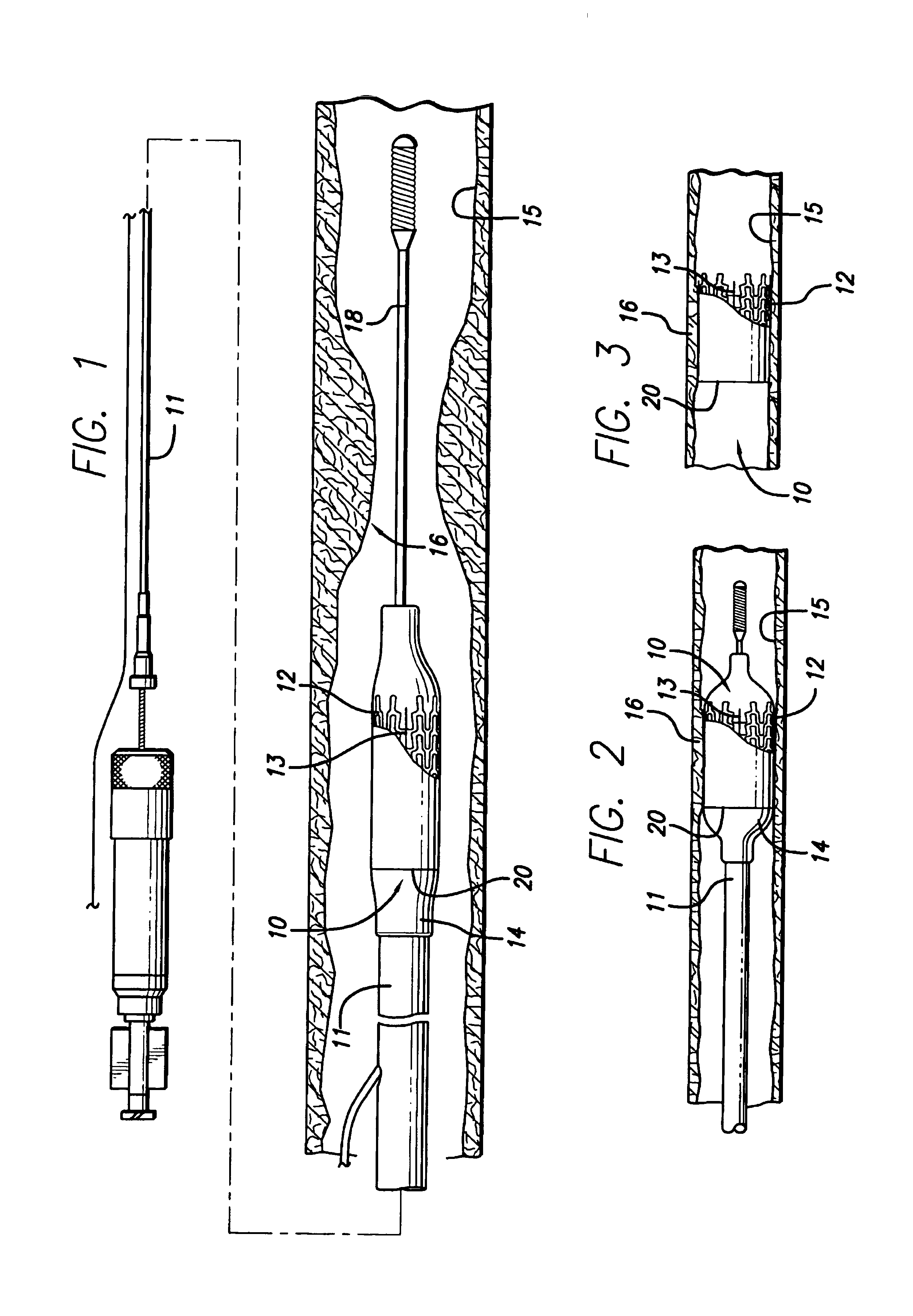
[0032]FIGS. 1-3 illustrate a first embodiment of a covered stent 10 incorporating features of the invention which is mounted onto a delivery catheter 11. The covered stent generally comprises a plurality of radially expandable cylindrical elements 12 disposed generally coaxially, interconnected by interconnecting members 13 disposed between adjacent cylindrical elements and covered with polymeric material. The delivery catheter has an expandable portion or balloon 14 for expanding the covered stent within an artery 15 or other vessel. The artery, as shown in FIG. 1, has a lesion 16 which has occluded a portion of the arterial passageway.

[0033]The delivery catheter onto which the covered stent is mounted is essentially the same as a conventional balloon dilatation catheter for angioplasty procedures. The balloon may be formed of suitable materials such as polyethylene, polyurethane, PEBAX, polyethylene terephthalate, polyvinyl chloride, nylon and ionomers such as Surlyn® manufactured...


PUM


Abstract

A polymeric material such as polyurethane, PET, or ePTFE is used to cover an intravascular stent. The cover material has an overlapping portion which is slidable upon itself so that when the stent is expanded, the cover material does not contribute to stent foreshortening, if any. The cover material can be provided with holes to permit endothelialization and can be drug loaded to facilitate repair of a damaged vessel.

Description

BACKGROUND OF THE INVENTION[0001]The present invention relates generally to expandable endoprosthesis devices, generally called stents, which are adapted to be implanted into a patient's body lumen, such as a blood vessel, to maintain the patency thereof, and more particularly to covered vascular stents which can minimize plaque prolapse that can occur between the struts of the stent and can help prevent the formation and release of embolic debris into the body lumen. Stents are particularly useful in the treatment and repair of blood vessels after a stenosis has been compressed by percutaneous transluminal coronary angioplasty (PTCA), percutaneous transluminal angioplasty (PTA), or removed by atherectomy or other means, to help improve the results of the procedure and reduce the possibility of restenosis. Stents also can be used to provide primary compression to a stenosis in cases in which no initial PTCA or PTA procedure is performed. While stents are most often used in the proce...

Claims


Application Information

Patent Timeline
IPC IPC(8): A61F2/06A61B17/00A61F2/84
CPCA61B17/00234A61F2/07A61B17/00491A61B17/0057A61F2/958A61F2002/075A61F2/89
Inventor DANG, KENNY L.JUANTA, HANMATIN, NAZANINE
Owner ABBOTT CARDIOVASCULAR
Learn More