Matrix-free desorption ionization mass spectrometry using tailored morphology layer devices

a morphology layer and mass spectrometry technology, applied in the field of customized morphology material systems, can solve the problems of complex spectrum analysis, limited application of the most popular and widely used laser-based technique, maldi (matrix-assisted laser desorption-ionization), and matrix molecules themselves providing background in the signal

Inactive Publication Date: 2006-10-17
PENN STATE RES FOUND
View PDF22 Cites 19 Cited by
  • Summary
  • Abstract
  • Description
  • Claims
  • Application Information

AI Technical Summary

Benefits of technology

[0017]The present invention is directed to a class of layered structures comprising one or more layers, with tailored application-specific morphology, for use in light desorption-ionization mass spectrometry. This class of structures holds analytes and allows them to be desorbed and ionized in the presence of a light source for subsequent mass analysis. Analytes are preferably in an am

Problems solved by technology

However, with recent demands in throughput and small molecule screening, the most popular and widely used laser-based technique, known as MALDI (matrix-assisted laser desorption-ionization), has limitations.
However, for small molecules (approximately 500 amu and below, such as drug molecules), the matrix molecules themselves provide background in the signal and complicate spectrum analysis.
Furthermore, with modern demands in automation, throughput and reproducibility, the addition of the matrix to the analyte and its preparation become issues particularly in the case of throughput.
These limitations were recognized during the onset of MALDI, leading to the study of non-matrix methods.
Problems with all these matrix-less light desorption techniques reported in the literature include a high degree of molecular fragmentation and a very limited mass range.
These studies, and recent comments, maintain that smooth (non-porous) surfaces do not work effectively for matrix-less laser mass desorption.
A recent report supports the understanding that smooth surfaces do not functi

Method used


Image

  • Matrix-free desorption ionization mass spectrometry using tailored morphology layer devices
  • Matrix-free desorption ionization mass spectrometry using tailored morphology layer devices
  • Matrix-free desorption ionization mass spectrometry using tailored morphology layer devices

Examples


Embodiment Construction

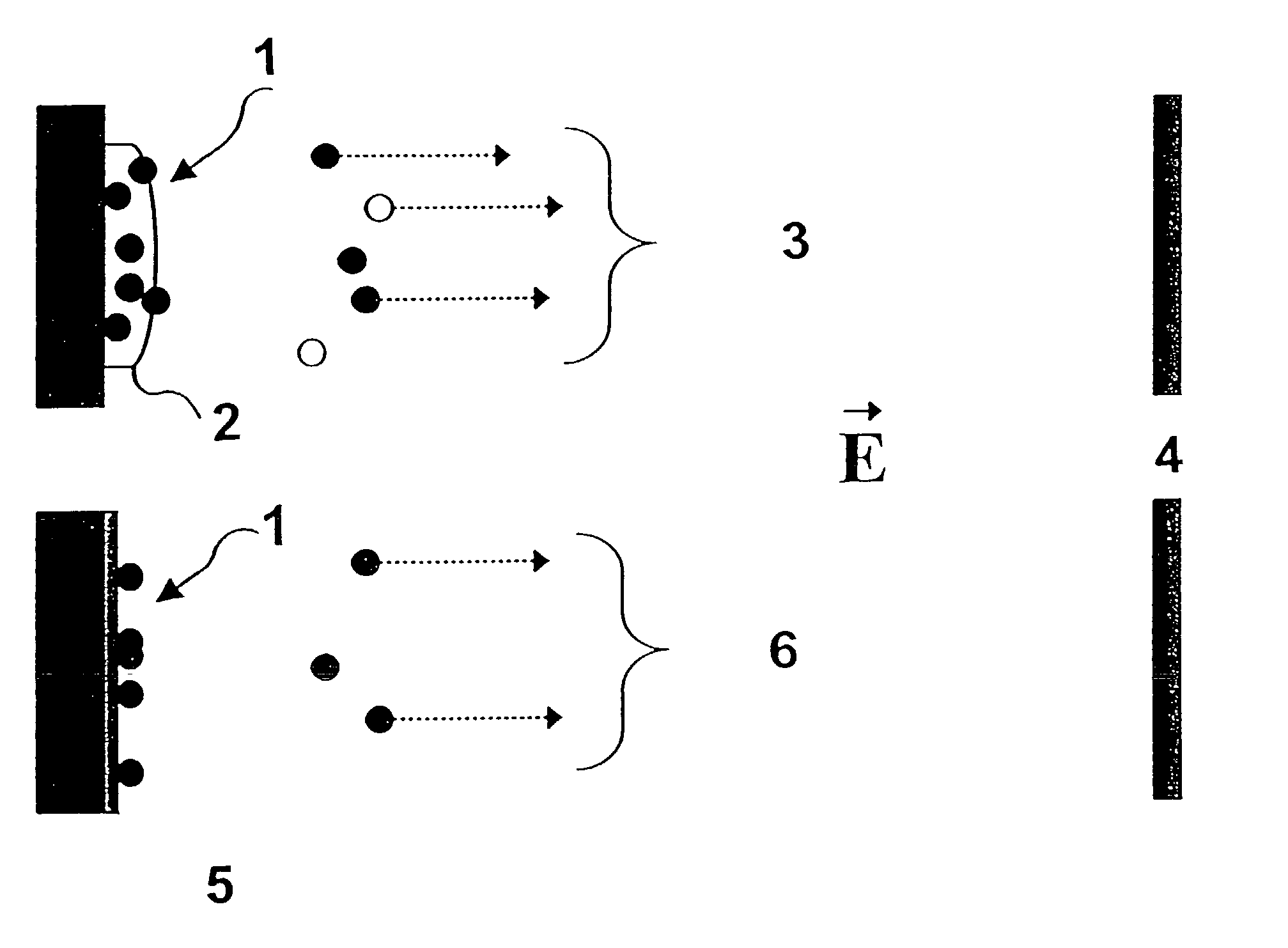
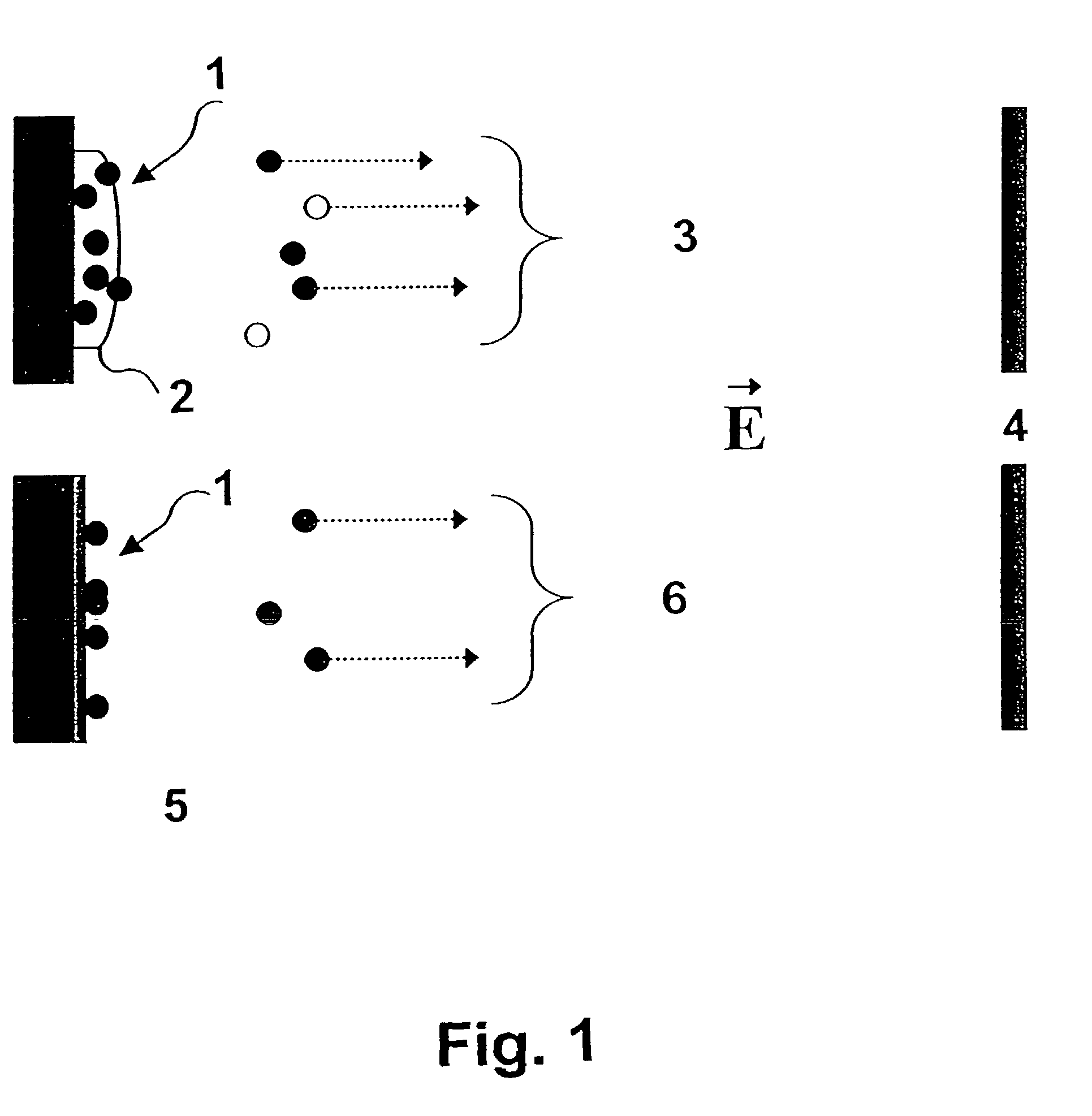
[0029]Referring now to FIG. 1, there is shown a schematic representation of the MALDI and the method of the present invention. Ultra-violet light (337 nm) 1 impinges matrix 2 to provide sample and matrix ions and neutrals 3 to reach detector 4.

[0030]Referring now to FIG. 5 which shows devices of various materials, FIG. 5a shows a device having a high surface area to volume ratio film or layer of columnar silicon 11 on a plastic substrate 10. The functions of the columnar silicon layer 11 are absorption, optical coupling, and immobilization. Advantages of this device include, but are not limited to, one-step production, inexpensive substrate material, and high molecular immobilization.

[0031]FIG. 5b shows a device having a layer of silicon dioxide 15 on a layer of amorphous silicon 12, on a layer of metal 13, on a glass substrate 14. The function of the amorphous silicon layer 12 is light absorption. The metal 13 and silicon dioxide 15 provide optical coupling; also, the silicon dioxi...


PUM

PropertyMeasurementUnit
Thicknessaaaaaaaaaa
Thicknessaaaaaaaaaa
Thicknessaaaaaaaaaa

Abstract

There is disclosed an apparatus for providing an ionized analyte for mass analysis by photon desorption comprising at least one layer for contacting an analyte, and a substrate on which said layer is deposited. Upon irradiation of said apparatus, said analyte desorbs and ionizes for analysis by mass spectrometry. The layer or layers of said apparatus comprise a continuous film, a discontinuous film or any combinations thereof.

Description

[0001]This application claims priority from U.S. Provisional Application No. 60 / 290,876, filed May 14, 2001, and is a continuation in part application of U.S. application Ser. No. 09 / 580,105, filed May 30, 2000 now U.S. Pat. No. 6,399,177. This application also claims priority from U.S. patent application Ser. No. 10 / 104,749, filed Mar. 22, 2002, which is a continuation of U.S. patent application Ser. No. 09 / 580,105, filed May 30, 2000. Priority is also claimed from U.S. application Ser. No. 09 / 836,449, filed Apr. 17, 2001, which is a continuation in part of U.S. patent application Ser. No. 09 / 739,940, filed Dec. 19, 2000, which is a continuation in part of U.S. patent application Ser. No. 09 / 580,105, filed May 30, 2000.BACKGROUND OF THE INVENTION[0002]1. Field of the Invention[0003]The present invention relates to tailored-morphology material systems and their use in molecular mass analysis by electromagnetic energy desorption-ionization mass spectrometry. Areas of interest for thi...

Claims


Application Information

Patent Timeline
IPC IPC(8): B01D59/44B81B3/00B81C1/00C23C16/24C23C16/511G01N1/04G01N1/34G01N1/40G01N21/17G01N27/447H01J49/04H01J49/16H01L51/00H01L51/30H01L51/42
CPCC23C16/24C23C16/511G01N1/405G01N21/17G01N27/44717H01J49/162Y10T428/24802H01L51/0038H01L51/4253Y10T436/25G01N2001/045Y10T428/31678H10K85/114H10K30/30
Inventor FONASH, STEPHEN J.KALKAN, ALI KAANCUIFFI, JOSEPHHAYES, DANIEL J.
Owner PENN STATE RES FOUND
Why Eureka
Try Eureka