

Process for recovery of pure acrylonitrile
a technology of acrylonitrile and purification process, which is applied in the direction of vacuum distillation separation, separation process, organic chemistry, etc., can solve the problems of forming different by-product contaminants, significant impurities, and the inability to universally interchange the purification process of acrylonitrile with resp
- Summary
- Abstract
- Description
- Claims
- Application Information
AI Technical Summary
Benefits of technology
Problems solved by technology
Method used
Image

Examples
example-1
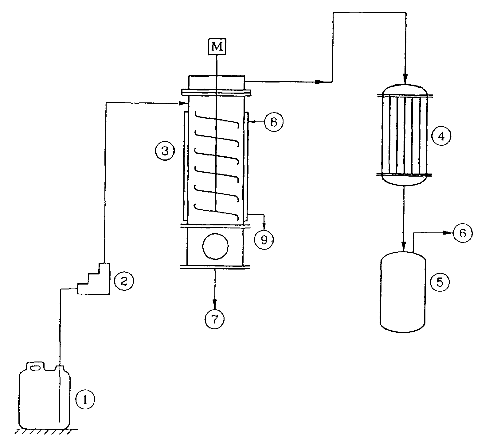
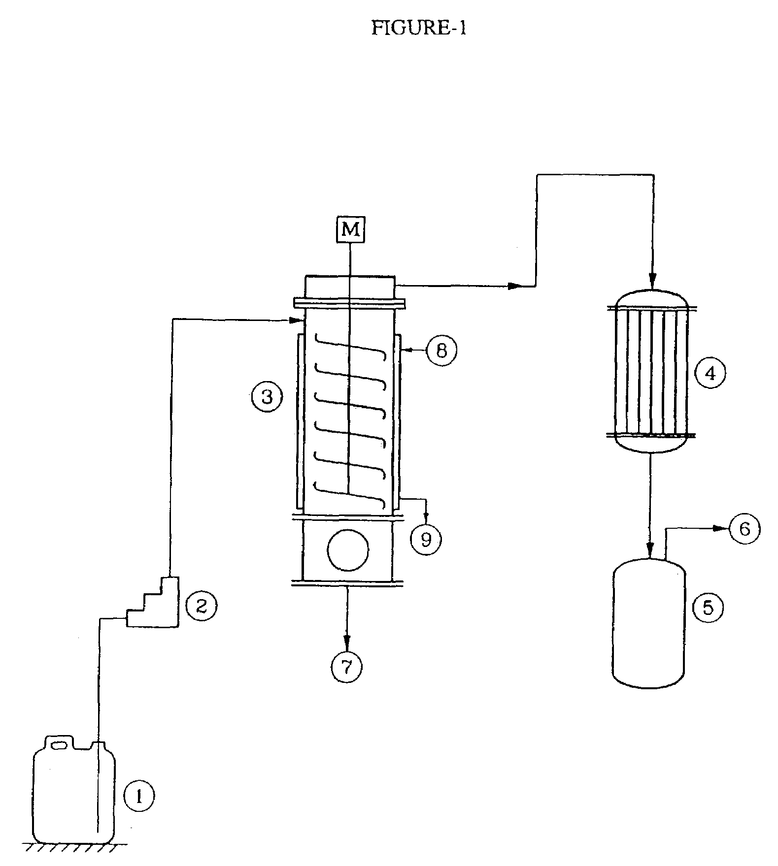
Using Pilot Plant as Shown in FIG. 1
[0045]The agitated thin film evaporator [ATFE] (3) as indicated in FIG. 1 was provided with a zero clearance agitator. The agitator speed was 800 RPM. The heat transfer area was 0.12 square meter. The jacket was provided with hot oil circulation. The distillate condenser was provided with ice water circulation. The contaminated acrylonitrile from (1) was fed to (3) by pump (2) at a rate of 10.5 kg / h. ATFE was maintained at 140° C. Total assembly was maintained under reduced pressure at 200 mm Hg abs, The product vapor was immediately evacuated into condenser (4) where it was condensed at low temperature by ice-chilled water, and collected in receiver (5). Operation was carried out at steady state for 1 hour. Temperature of the vapor exiting from (3) was 45° C. Residue temperature was 88° C. Residue on analysis showed 8900 ppm of Acrylonitrile and 3.4% as water content. Moisture content in distillate was found to be 4000 ppm, while acidity as sulfu...
example-2
Using Pilot Plant as Shown in FIG. 1
[0046]The agitated thin film evaporator [ATFE] (3) as indicated in FIG. 1 was provided with a zero clearance agitator. The agitator speed was 800 RPM. The heat transfer area was 0.12 square meter. The jacket was provided with hot oil circulation. The distillate condenser was provided with ice water circulation. The contaminated acrylonitrile from (1) was fed to (3) by pump (2) at a rate of 10.5 kg / h. The ATFE was maintained at 140° C. The total assembly was maintained under reduced pressure at 170 mm Hg abs, The product vapor was immediately evacuated into condenser (4) where it was condensed at low temperature by ice-chilled water, and collected in the receiver (5). The operation was carried out at steady state for 1 hour. Temperature of the vapor exiting from (3) was 43° C. The residue temperature was 92° C. The residue on analysis showed 9400 ppm of Acrylonitrile content Moisture content in distillate was found to be 3000 ppm, while acidity as ...
example-3
Using Pilot Plant as Shown in FIG. 1
[0047]The agitated thin film evaporator [ATFE] (3) as indicated in FIG. 1 was provided with a zero clearance agitator. The agitator speed was 800 RPM. The heat transfer area was 0.12 square meter. The jacket was provided with hot oil circulation. The distillate condenser was provided with ice water circulation. The contaminated acrylonitrile from (1) was fed to (3) by pump (2) at a rate of 10.5 kg / h. The ATFE was maintained at 146° C. The total assembly was maintained under reduced pressure at 200 mm Hg abs, The product vapor was immediately evacuated into condenser (4) where it was condensed at low temperature by ice-chilled water, and collected in the receiver (5). The operation was carried out at steady state for 1 hour. The temperature of the vapor exiting from (3) was 45° C. The residue temperature was 96° C. The residue on analysis showed 7300 ppm of Acrylonitrile content and 5.98% water by weight. The moisture content in distillate was foun...
PUM
| Property | Measurement | Unit |
|---|---|---|
| pressure | aaaaa | aaaaa |
| temperature | aaaaa | aaaaa |
| temperature | aaaaa | aaaaa |
Abstract
Description
Claims
Application Information