Hydrogen generating device having hydrogen separator membrane and control method therefor

a technology of hydrogen separator and generating device, which is applied in electrochemical generators, sustainable manufacturing/processing, transportation and packaging, etc., can solve the problems of heat generated during the reaction and can be diluted, and achieve the effect of avoiding suppressing hydrogen embrittlement of the hydrogen separator membrane in a low temperature condition, and facilitating warm-up of the hydrogen generating devi

Inactive Publication Date: 2006-11-07
TOYOTA JIDOSHA KK
View PDF9 Cites 2 Cited by
  • Summary
  • Abstract
  • Description
  • Claims
  • Application Information

AI Technical Summary

Benefits of technology

[0008]The invention has been made to solve the aforementioned problems, and it is an object of the invention to suppress hydrogen enbrittlement in the case where the hydrogen generating device is in a low temperature condition. It is a further object of the invention to suppress a thermal stress during the warm-up operation of the hydrogen generating device and to reduce a possibility of generation of cracks and damages on the hydrogen separator membrane.
[0010]According to the hydrogen generating device as structured above, hydrogen embrittlement of the hydrogen separator membrane in a low temperature condition can be suppressed. The “low temperature condition” refers to a condition in which a temperature of the hydrogen separating portion is lower than a predetermined temperature which is determined based on the material of the hydrogen separator membrane. Such a condition includes the starting of the device. The hydrogen suppressing portion can be structured so as to control the supply portion to cause an oxidation reaction by a lean burn operation in the reforming portion in the low temperature condition. In a condition where a large amount of oxygen exists, such as in a lean burn condition, partial oxidation will not occur. Most of the raw material is vaporized or becomes carbon dioxide by full oxidation or oxidation by burner, in other words, by burning. According to such control, generation of hydrogen is suppressed and adsorption of hydrogen to the hydrogen separator membrane will not occur, thereby avoiding the hydrogen embrittlement of the hydrogen separator membrane. Further, in this reaction, since a high temperature gas is generated, warm-up of the hydrogen generating device can be facilitated by supplying such high temperature gas.
[0011]By supplying a large amount of oxygen to the reforming portion, the following effects can also be obtained in accordance with the amount of oxygen supplied. First, carbon attached to the hydrogen separator membrane can be oxidized by the high temperature oxygen, and thereby the hydrogen separator membrane can be purified. Second, by supplying excessive oxygen or air for oxidation reaction, the heat generated during the reaction can be diluted. Accordingly, a temperature of the gas generated by the reaction can be substantially adjusted to the operation temperature of the reforming portion, and thus deterioration of catalyst caused by overheating during warm-up operation can be reduced. A sudden temperature rise of the hydrogen generating device can be avoided, and therefore generation of the thermal stress can also be reduced.

Problems solved by technology

Second, by supplying excessive oxygen or air for oxidation reaction, the heat generated during the reaction can be diluted.

Method used


Image

  • Hydrogen generating device having hydrogen separator membrane and control method therefor
  • Hydrogen generating device having hydrogen separator membrane and control method therefor
  • Hydrogen generating device having hydrogen separator membrane and control method therefor

Examples


first embodiment

A. First Embodiment

A1. System Structure

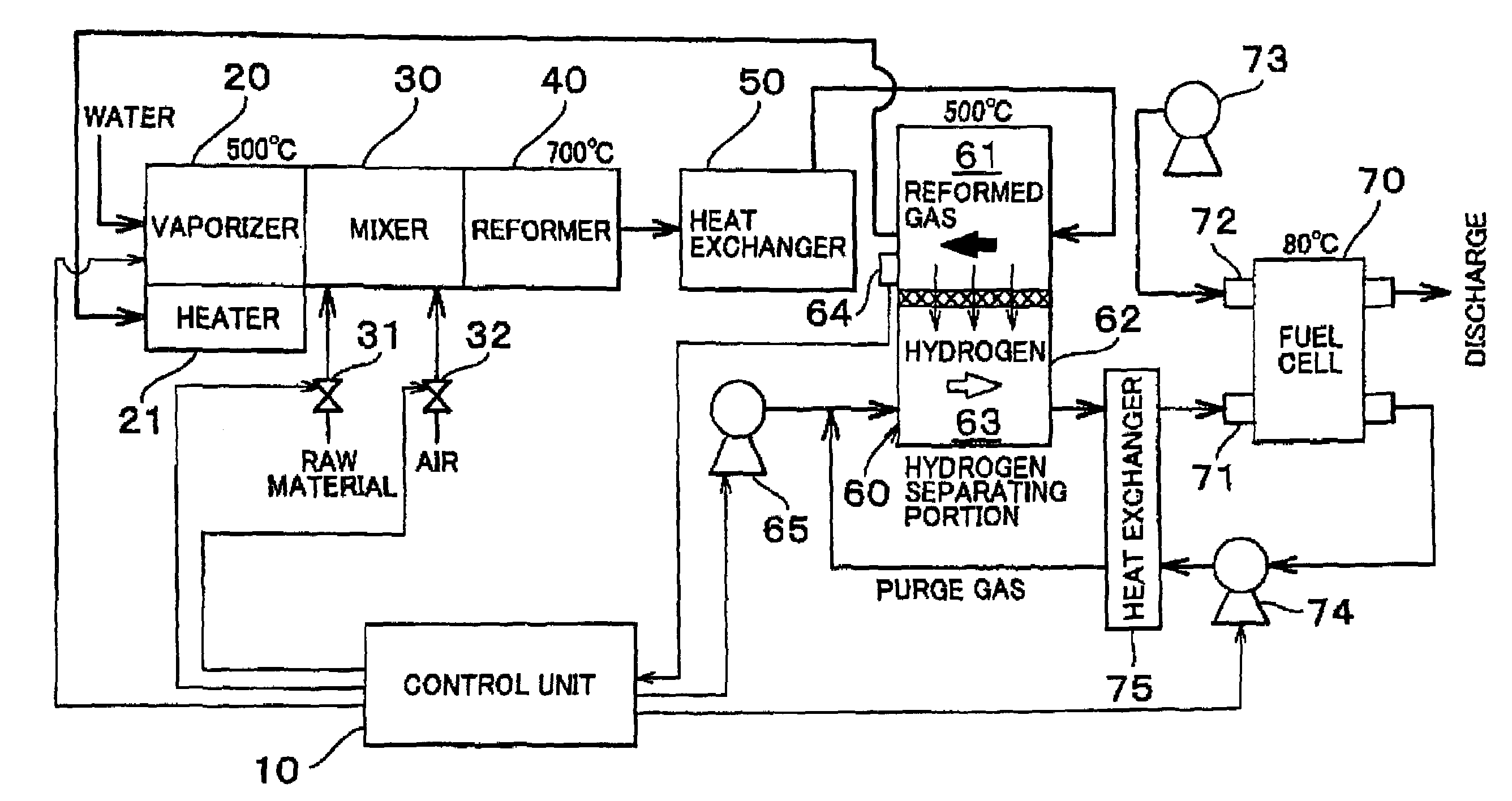
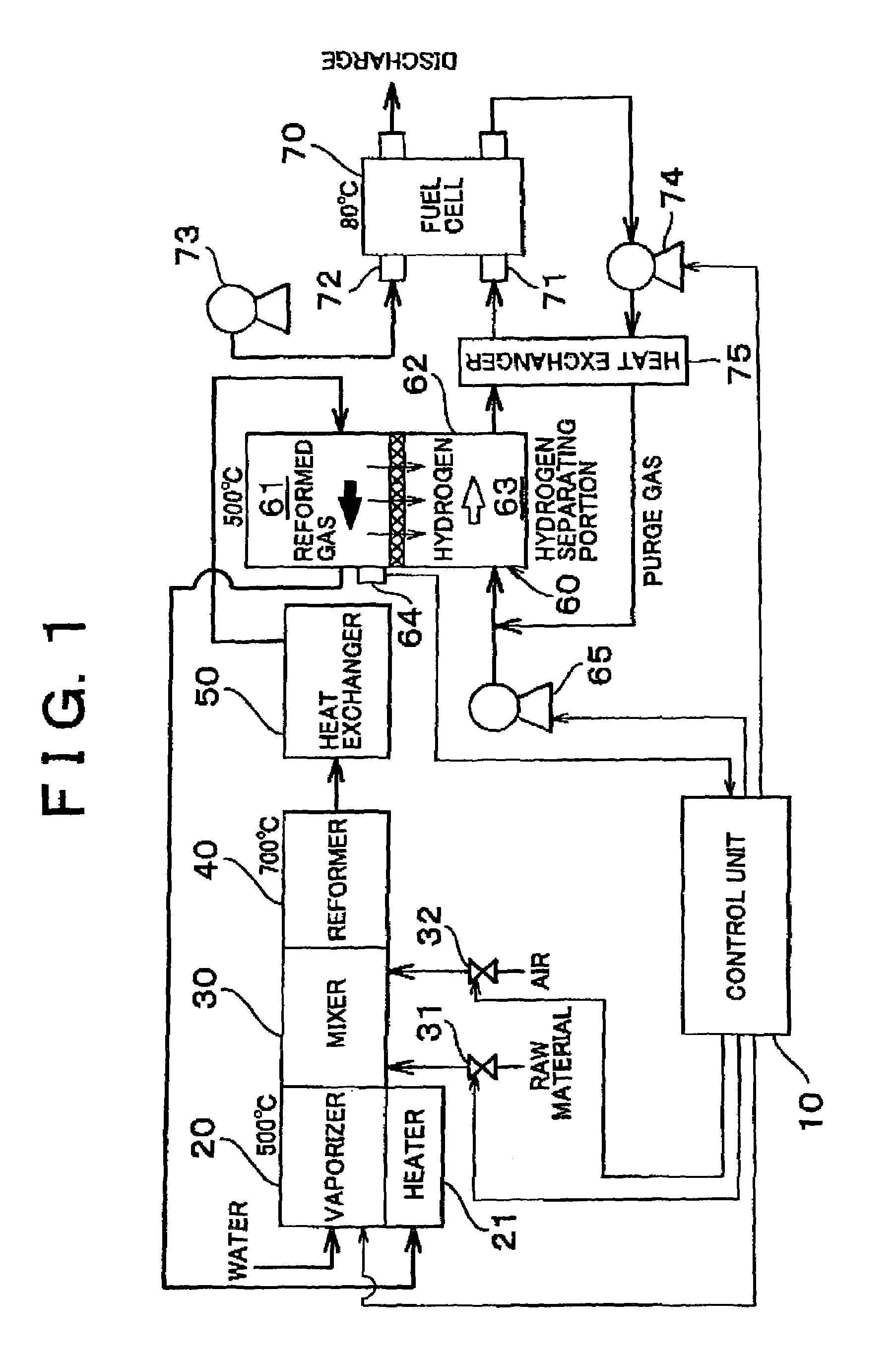
[0027]FIG. 1 is an explanatory view of a general structure of a fuel cell system according to a first embodiment The fuel cell system generates electric power by electrochemical reaction between hydrogen and oxygen supplied to a fuel cell 70. Compressed air supplied to a cathode 72 by blower 73 is used as oxygen to be supplied. Hydrogen is generated by reforming a raw material by a hydrogen generating device which will be explained below, and is supplied to an anode 71. The raw material to be used can be selected from various carbon hydrogen fuels, which can generate hydrogen by reforming reaction, for example, liquid carbon hydrogen such as gasoline, alcohol such as methanol, aldehyde, or natural gas.

[0028]The raw material and water (not shown) are respectively stored in a tank which serves as a supply portion. The water is first vaporized and heated to about 500° C. in a vaporizer 20, and then supplied to a mixer 30. The raw material and air ...

second embodiment

B. Second Embodiment

B1. System Structure

[0061]FIG. 5 shows an explanatory view of a general structure of a fuel cell system according to a second embodiment. The structure is almost the same as that in the first embodiment, except that the air can be supplied between the reformer 40 and the hydrogen separating portion 60. The amount of air supply is controlled by the control unit 10A by adjusting the opening degree of a valve 41. This embodiment illustrates a case in which the air is supplied between the reformer 40 and the heat exchanger 50. However, the structure may be such that the air may be supplied between the heat exchanger 50 and the hydrogen separating portion 60.

B2. Starting Control Process

[0062]FIG. 6 shows a flow chart for a starting control process according to the second embodiment. As is the case with the first embodiment, the threshold temperatures are set to 300° C. and 500° C., and the control is executed in three phases. In the second embodiment, the process in t...


PUM

PropertyMeasurementUnit
temperatureaaaaaaaaaa
threshold temperaturesaaaaaaaaaa

Abstract

When the hydrogen separating membrane is in a low temperature condition, a lean bus operation is carried out in a reformer in order to conduct warm-up while suppressing generation of hydrogen. At the timing t1 where the temperature of the hydrogen separator membrane has reached a temperature at which hydrogen embrittlement does not occur, reforming is initiated. In such a condition, oxygen is supplied to hydrogen which is permeated through the hydrogen separator membrane for burning the hydrogen, so as to further facilitate the warm-up. At the timing t2 where the temperature has reached an operation temperature, the supply of oxygen in a purge side is stopped so as to stop the burning of hydrogen, and an operation mode is shifted to a normal operation.

Description

INCORPORATION BY REFERENCE[0001]The disclosure of Japanese Patent Application No. 2001-288040 filed on Sep. 21, 2001 including the specification, drawings, and abstract is incorporated herein by reference in its entirety.BACKGROUND OF THE INVENTION[0002]1. Field of the Invention[0003]The invention relates to a hydrogen generating device and a control method therefor for generating a hydrogen-rich gas by separating hydrogen from a reformed gas, which is obtained by reforming a predetermined raw material, using a hydrogen separator membrane.[0004]2. Description of the Related Art[0005]A fuel cell, which generates electric power by electro-chemical reaction between hydrogen and oxygen, has recently been gaining attention as an energy source. The fuel cell generates an electromotive force by the electro-chemical reaction between hydrogen and oxygen. The hydrogen to be supplied to the fiel cell is generated by a hydrogen generating device by reforming a raw material, such as hydrocarbon ...

Claims


Application Information

Patent Timeline
Patent Type & Authority Patents(United States)
IPC IPC(8): B01J8/00C01B3/32B01B1/00B01J19/00C01B3/34C01B3/38C01B3/50C01B3/56H01M8/04H01M8/06
CPCC01B3/38C01B3/501H01M8/0662B01J19/0006B01B1/005Y10T428/24083B01J2219/00006B01J2219/00191C01B2203/0244C01B2203/0405C01B2203/047C01B2203/0475C01B2203/0495C01B2203/066C01B2203/0811C01B2203/0822C01B2203/0827C01B2203/0844C01B2203/0883C01B2203/1211C01B2203/1223C01B2203/1241C01B2203/1276C01B2203/1288C01B2203/142C01B2203/1604C01B2203/1619C01B2203/169C01B2203/82H01M8/04097H01M8/0612H01M8/0687Y02E60/50Y02P20/10
Inventor AOYAMA, SATOSHISATO, HIROMICHINAKATA, TOSHIHIDEITO, NAOKI
Owner TOYOTA JIDOSHA KK
Why Eureka
Try Eureka