MEMS-based optical wireless communication system

a wireless communication and optical wireless technology, applied in electromagnetic transmission, electrical equipment, transmission, etc., can solve the problems of limited field of view (fov) of optical receiver systems, large and cumbersome units, and high cost, and achieve effective and reliable optical communication links

Inactive Publication Date: 2006-12-05
TZENG PAUL +1
View PDF1 Cites 17 Cited by
  • Summary
  • Abstract
  • Description
  • Claims
  • Application Information

AI Technical Summary

Benefits of technology

[0023]In view of the above disclosure the primary object of the invention is to produce a MEMS-based optical, wireless communication system that can provide an effective and reliable optical communication link between at least two line-of-sight systems.

Problems solved by technology

However, one significant drawback with FSO transceivers which has resulted in higher than expected cost and has forced units to be large and cumbersome is that once the transmit optical beams of the units have been aimed at the opposing receivers, motion in the platform supporting either unit or the influence of atmospheric air currents can be large enough to move either beam off the respective receiver aperture and thereby momentarily sever the data link.
Another drawback is that to attain high-speed operation, the physical diameter of photosensitive receivers must be a fraction of a millimeter, thus leading to limitations on the Field of View (FOV) for the optical receiver systems.
However, moving the beam along does nothing to resolve the problem of support motion moving the received beam outside the FOV of the receiver.
Herein lies a design problem related to the time scales of the motions introduced by a building, the support structure which attaches the unit to the building and the movement due to atmospheric currents which limits the ability to use the aforementioned beam steering approach.
As a result, these motions cause changes over many minutes or hours.
The influence of atmospheric air currents on an optical beam is fairly complicated and depends on momentary fluctuations in air temperature and speed but typically causes movement of the beam position on time scales similar to that outlined above for vibration.
The difficulty that these motion time scales produce is that the maximum speed of movement of the mirror, and hence the motions that can be compensated for, is limited by the mechanical resonance frequency of the mirror and its movement mechanism which is related to the physical size and mass of the mirror.
Thus, these mirror systems cannot compensate for mount vibration or atmospheric influences.
The result is that these systems can typically only compensate for overall building movement.
A further difficulty with implementing a motion tracking system is sensing the beam motion with sufficient precision at the opposing receiver in the presence of more intense light sources in the wavelength region of the laser transmitter, such as the sun.
However, due to the relatively small size of these type of detectors relative to the typical receiver aperture diameter, a focusing lens or reducing telescope is needed to relay the sample of the received beam, which makes the sensing system fundamentally insensitive to the beam position.
An additional difficult with this system is that sunlight can enter the receiver aperture at an angle near the angle joining the units and fall unevenly on the segmented “position” sensor, thus causing the sensor signal to erroneously represent the beam source angle to be different from that of the transmitted beam.
The size of the segments tend to be large enough that the response speed is much slower than the pulses representing the modulated transmit beam, so there is no possibility of distinguishing the signal due to light from the beam or from the sun, despite wavelength selective filtering.

Method used


Image

  • MEMS-based optical wireless communication system
  • MEMS-based optical wireless communication system
  • MEMS-based optical wireless communication system

Examples


Embodiment Construction

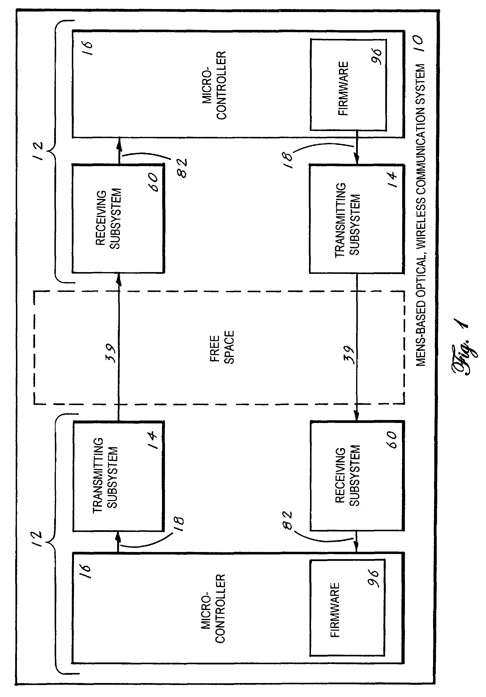
[0039]The best mode for carrying out the invention is presented in terms of a preferred embodiment for a Micro Electromechanical System (MEMS)-Based, Optical, Wireless Communication System 10, (hereinafter “MBOWCS 10”). The MBOWCS 10, as shown in FIGS. 1–6, is designed to provide optical, wireless communication between two or more locations by utilizing the MBOWCS 10 in combination with data inputs provided by existing telecommunication equipment.

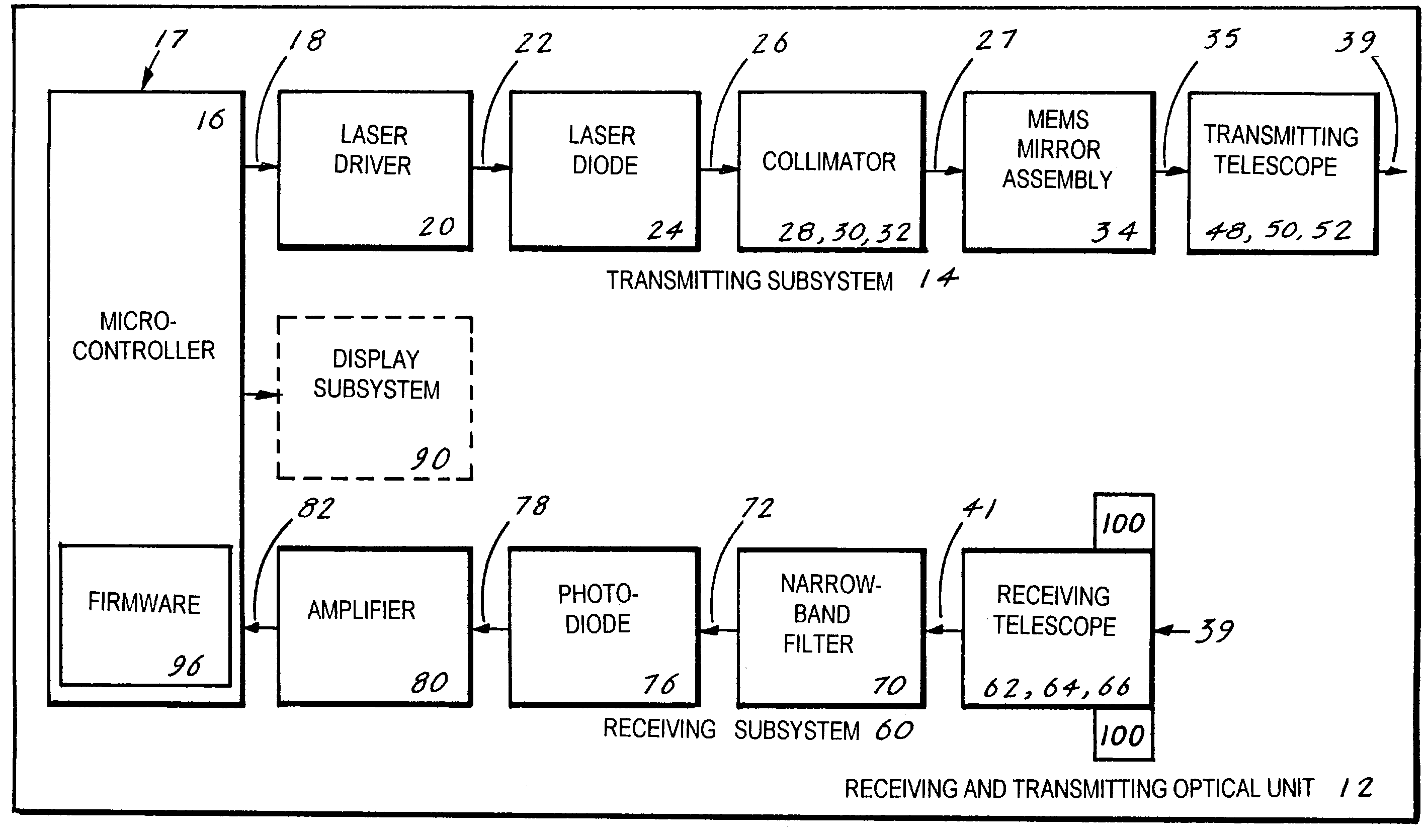
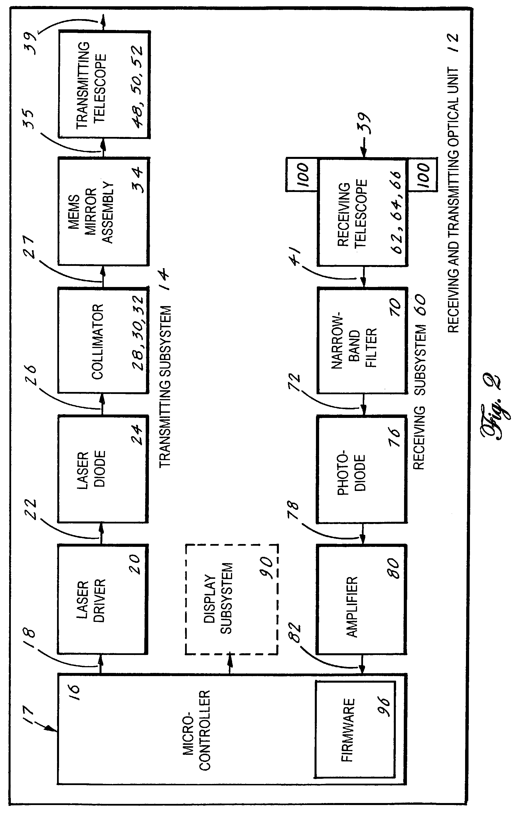
[0040]The MBOWCS 10, as shown in FIG. 1, consists of at least two receiving and transmitting optical units 12. Each unit 12 is comprised of a transmitting subsystem 14, a receiving subsystem 60, and a microcontroller 16 that is operated by a firmware program 96.

[0041]The transmitting subsystem 14 has means for receiving an input data signal 17 and transmitting a corresponding modulated laser beam 39 through free space. The receiving subsystem 60 has means for receiving the modulated laser beam 39 from the transmitting subsystem 14, sensing ...


PUM


Abstract

A MEMS-based optical, wireless communication system (10) that is comprised of a receiving and transmitting optical unit (12) that is further comprised of a transmitting subsystem (14) and a receiving subsystem (60), both of which are controlled by a microcontroller (16) and firmware (96). The system (10) is designed to allow a first unit (12) to transmit through free space a modulated laser beam (39) that is received by a second unit (12) located within line-of-sight of the first unit (12). Conversely, the second unit (12) can likewise transmit a modulated laser beam (39) that is received by the first unit (12) or other line-of-sight units (12). The system (10) features a MEMS mirror assembly (34) that operates in combination with a quad sensor (100). The combination allows fast, precise tracking and compensates for atmospheric disturbances associated with optical communication namely, building sway, wind and scintillations caused by changes in the refraction index of the atmosphere.

Description

[0001]This application claims the benefit of Provisional Application No. 60 / 372,046 filed Apr. 12, 2002.TECHNICAL FIELD[0002]The invention pertains to the general field of free space optical communication systems and more particularly to an optical, wireless communication system that incorporates a MEMS mirror. The MEMS mirror compensates for mechanical movement and atmospheric aberrations to provide a stable optical transmission and receiving system.BACKGROUND ART[0003]With the explosive growth of information services related to the “world wide web” in the last decade and the increasing demand for high resolution color graphic art and video in the material being presented therein, a demand for high data rate interconnects which are rapidly deployable, flexible and of minimum cost has been generated. With the high costs peripheral to the process of deploying fiber optics to satisfy this demand and the lack of flexibility in networks using fiber optics or other physically fixed insta...

Claims


Application Information

Patent Timeline
Patent Type & Authority Patents(United States)
IPC IPC(8): H04B10/00
CPCH04B10/1127
Inventor TZENG, PAULBLAIR, RANDALL J.
Owner TZENG PAUL
Why Eureka
Try Eureka