
Permanent magnet type rotor and method of manufacturing the rotor

a permanent magnet type, rotor technology, applied in the direction of magnetic circuits characterised by magnetic materials, magnetic circuit rotating parts, magnetic circuit shapes/forms/construction, etc., can solve the problems of low strength, rotor weight and size increase, and brittle silicon steel plate, etc., to achieve good balance, increase the bonding rate between the outer member and the inner member, and improve the effect of weigh

Inactive Publication Date: 2006-12-19
HITACHI POWDERED METALS COMPANY +1
View PDF28 Cites 7 Cited by
  • Summary
  • Abstract
  • Description
  • Claims
  • Application Information

AI Technical Summary

Benefits of technology

The present invention provides a permanent magnet type rotor with a hollow shape that reduces weight without reducing magnetic characteristics. The inner member is made from a material with high strength, while the outer member is made from a sintered material. The inner and outer members are mutually diffusion-bonded together, resulting in a strong bond. The rotor has high efficiency and can be used in a high-speed engine. The manufacturing method involves fitting a green compact for the inner member into an outer member, sintering both to integrate them, and disposing permanent magnets on the outer member. The green compact for the inner member has a composition that matches the inner member and the outer member in thermal expansion. The outer member can be made from an ingot steel or a green compact. The invention provides a solution for reducing weight and improving efficiency of permanent magnet type rotors.

Problems solved by technology

However, silicon steel plate is brittle and low in strength, and reinforcing measures are required to obtain a necessary strength, and hence, the rotor is increased in its weight and size.
It is difficult to employ a hollow shape to reduce the rotor weight since the strength will be insufficient.
However, the S45C material has a high carbon content, and the magnetic characteristics are insufficient and satisfactory function as a dynamo or a motor cannot be obtained.

Method used


Image

  • Permanent magnet type rotor and method of manufacturing the rotor
  • Permanent magnet type rotor and method of manufacturing the rotor
  • Permanent magnet type rotor and method of manufacturing the rotor

Examples


first example

[0069]A green compact for an inner member was prepared by using an iron powder to which was added a powder containing a copper powder: 1.5% by mass, a graphite powder: 1.0% by mass, and zinc stearate as a forming lubricant, and compressing the mixed powder to a density of 6.5 g / cm3 into a shape as shown in FIG. 7. In FIG. 7, the unit is millimeter. Outer member was prepared by using an iron powder to which was added zinc stearate as a forming lubricant, and compressing the mixed powder to a density of 7.0 g / cm3 into in a shape as shown inFIG. 7 to obtain a green compact for an outer member 71. Another outer member was prepared by sintering the green compact for an outer member in nitrogen atmosphere at 850° C. for 30 minutes. Moreover, a pure iron ingot steel in a shape as shown in FIG. 7 was prepared as an ingot steel for an outer member.

[0070]The green compact for an inner member was tightly fitted into the green compact for an outer member, the sintered compact for an outer membe...

second example

[0074]A green compact for an inner member was prepared by using an iron powder to which was added a powder containing a copper powder: 1.5% by mass, a graphite powder: 1.0% by mass, and zinc stearate as a forming lubricant, and compressing the mixed powder to a density of 6.5 g / cm3 into a shape as shown in FIG. 7. For the outer member, an iron powder (Fe powder); an Fe-20Si powder containing Si: 20% by mass, and the balance of Fe and inevitable impurities; an Fe-20P powder containing P: 20% by mass %, and the balance of Fe and inevitable impurities; an Fe-0.6P powder containing P: 0.6% by mass, and the balance of Fe and inevitable impurities; Fe-20B powder containing B: 20% by mass, and the balance of Fe and inevitable impurities; and a copper powder (Cu powder) were prepared. These powders were mixed together with zinc stearate in the blending ratios shown in Table 2, and the obtained mixed powder for forming an outer member in the composition as shown in Table 2 were compressed in...

third example

[0078]Green compacts for an inner member and green compacts for an outer member were prepared in the same conditions as in the first example, and were fitted and integrated with in the fitting differences or interferences as shown in Table 3. Then, these were sintered in the same conditions as in the first example, and the bonding strength and the magnetic characteristics were evaluated, and the results are shown in Table 3.

[0079]

TABLE 3InnermemberOuterCompositionFe-1.5Cu-1.0CmemberCompositionFeFitting+10+5−60−375−400differenceμmμmμmμmμm(Interference)Passing fitTightening fitBrokenBonding strengthΔ◯◯◯—Magnetic characteristics (B)◯◯◯◯—

[0080]As is clear from Table 3, in the passing fit with a fitting difference 5 ì m, a favorable bonding strength was obtained, but in the passing fit with a gap of 10 ì m, sufficient bonding was not obtained and the bonding strength was reduced. In this test, when the diameter of the contacting surface was 150 mm, a favorable bonding strength was obtain...


PUM

PropertyMeasurementUnit
saturated magnetic flux densityaaaaaaaaaa
temperatureaaaaaaaaaa
densityaaaaaaaaaa

Abstract

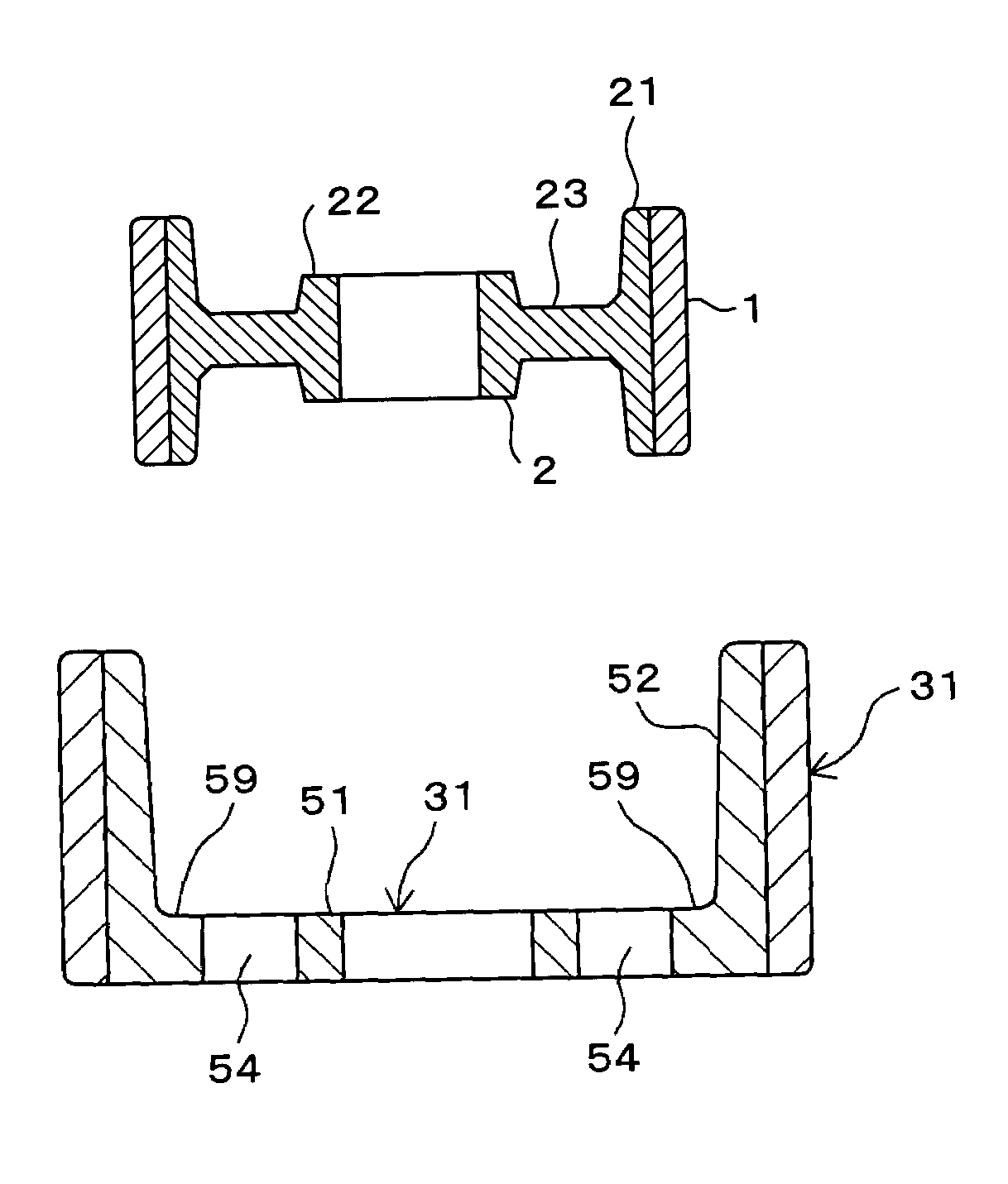
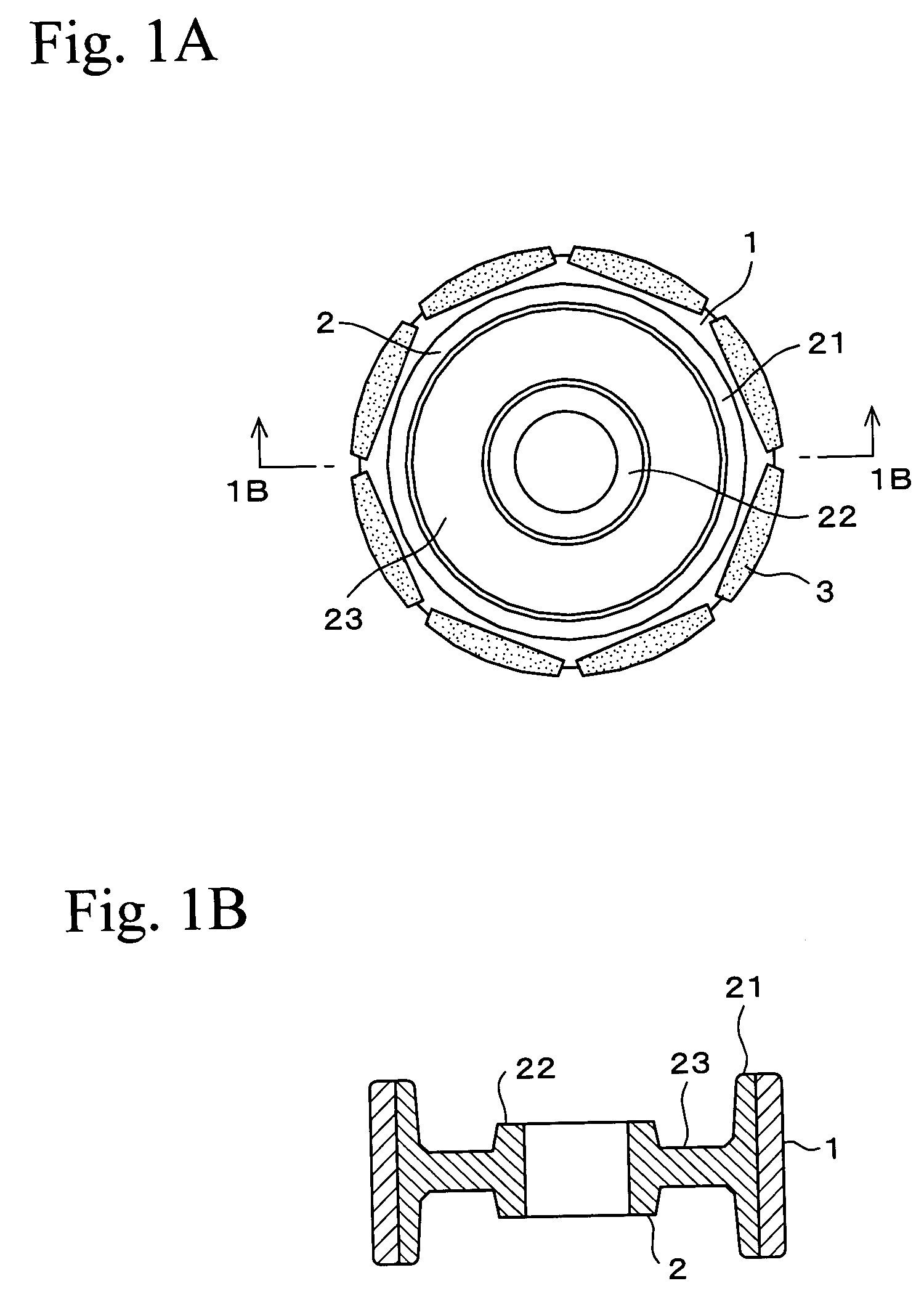
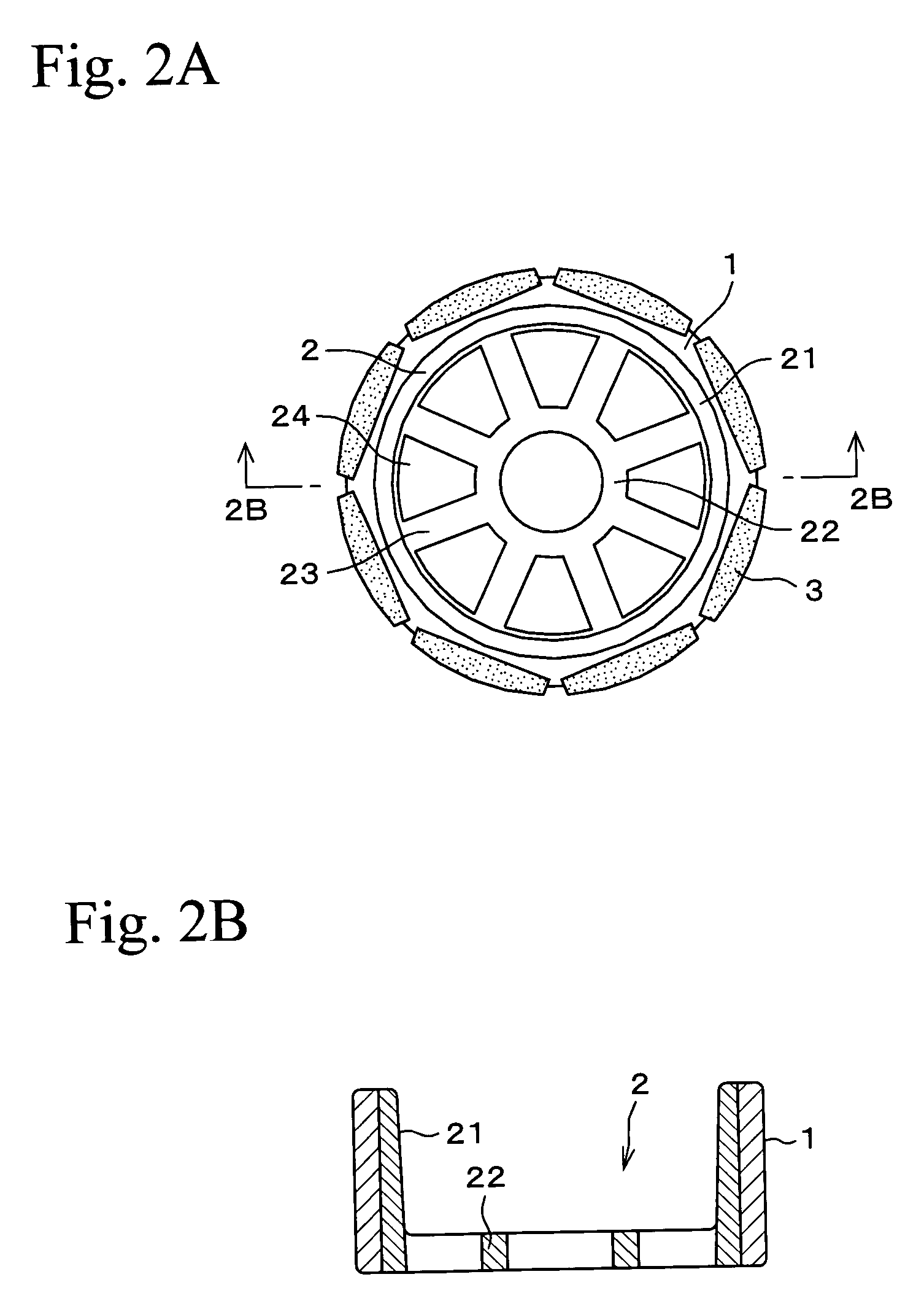
A permanent magnet type rotor comprises an inner member 2 having an outer ring portion 21; an approximately annular outer member 1 having soft magnetism and an inner circumference contacting with an outer circumference of the outer ring portion; and plural permanent magnets 3 disposed at equal intervals on the outer circumference of the outer member toward the circumferential direction. At least one of the inner member 2 and the outer member 1 is made from a sintered material, and the inner member 2 and the outer member 1 are mutually sintered and bonded. Thickness and weight of a dynamotor itself can be reduced and high output and high efficiency can be achieved.

Description

FIELD OF THE INVENTION[0001]The present invention relates to a permanent magnet type rotor having a permanent magnet disposed on a rotor surface, and relates to a manufacturing method therefor, and more particularly, the present invention relates to a technology for enhancing the magnetic characteristics and strength of the rotor.DESCRIPTION OF THE RELATED ART[0002]A permanent magnet type rotor used in a dynamotor mounted in an electric vehicle or a hybrid vehicle is required to have magnetic characteristics of high performance and high productivity. As materials for such a permanent magnet type motor, hitherto, silicon steel plate has been used. Since the rotor is tightened and fixed to the engine shaft, it is required to have high strength and hardness in order to be tightened firmly. However, silicon steel plate is brittle and low in strength, and reinforcing measures are required to obtain a necessary strength, and hence, the rotor is increased in its weight and size. It is diff...

Claims


Application Information

Patent Timeline
Patent Type & Authority Patents(United States)
IPC IPC(8): H02K21/12H01F41/02H02K1/02H02K1/27H02K15/03
CPCH01F41/0266H02K15/03H02K1/278H02K1/02Y10T29/49012H02K1/2781
Inventor ASAKA, KAZUOARAKAWA, TOMOAKIKAGAYA, TSUYOSHISHINZAKI, SATORUSATO, HIROMITSUFUKUDA, KENJIOGAWA, HIROHISAHORIE, TATSUROOKAMURA, AKIHIROSATO, KATSUAKIKOMATSU, TOSHIYASUNAKAHARA, YOUICHI
Owner HITACHI POWDERED METALS COMPANY
Learn More