Method and apparatus for parallel dispensing of defined volumes of solid particles

a technology of solid particles and parallel dispensing, which is applied in the direction of article feeders, lab clamping means, water/sand/air baths, etc., can solve the problems of affecting the stability of high-throughput systems, bottlenecks that hinder increased throughput, and pin tools that can be problematic for high-throughput systems, etc., to achieve the effect of increasing stability and shelf li

Active Publication Date: 2007-01-09
AGENA BIOSCI +1
View PDF136 Cites 26 Cited by
  • Summary
  • Abstract
  • Description
  • Claims
  • Application Information

AI Technical Summary

Benefits of technology

[0025]A sample preparation system constructed in accordance with the invention provides an automated process that dispenses appropriate amounts of solid material into wells of a microtiter plate for mixing into a suspension. The system utilizes an array of hollow tubes that are lowered into a particle reservoir such that particle material is forced up into the tubes. During loading, solid plungers in the tubes are positioned a known distance from the open end of the tubes. When the particle material is to be dispensed, the plungers are lowered to push the par...

Problems solved by technology

Some stations may take more time to complete than others, thereby creating a bottleneck that hinders increased throughput.
Pin tools can be problematic for high throughput systems because the pins themselves may have to be changed if different sample volumes are desired, or if the nature of the liquid sample is changed.
This causes a disruption in operation because, to ensure accurate transfer, another manual alignment must be performed before proceeding with the processing run.
The samples will not be accurately transferred to the target locations on the chip.
Thus, changing pins or pin blocks results in not only a delay because of the alignment process, but also results in a more complicated alignment process, further slowing down the system throughput.
It should be apparent that current alignment techniques cannot easily support the demands of high-throughput systems.
Therefore, systems stagger the delivery of sample material with repeated cycles of loading and printing with the pins in a dispensing head.
It should be apparent that the current staggered printing operation can be a bottleneck to increasing the throughput of sam...

Method used


Image

  • Method and apparatus for parallel dispensing of defined volumes of solid particles
  • Method and apparatus for parallel dispensing of defined volumes of solid particles
  • Method and apparatus for parallel dispensing of defined volumes of solid particles

Examples


Embodiment Construction

[0076]Unless defined otherwise, all technical and scientific terms used herein have the same meaning as is commonly understood by one of skill in the art to which this invention belongs. All patents, patent applications, published applications and publications, Genbank sequences, Websites, and other published material referred to throughout the entire disclosure herein are, unless noted otherwise, incorporated by reference in their entirety.

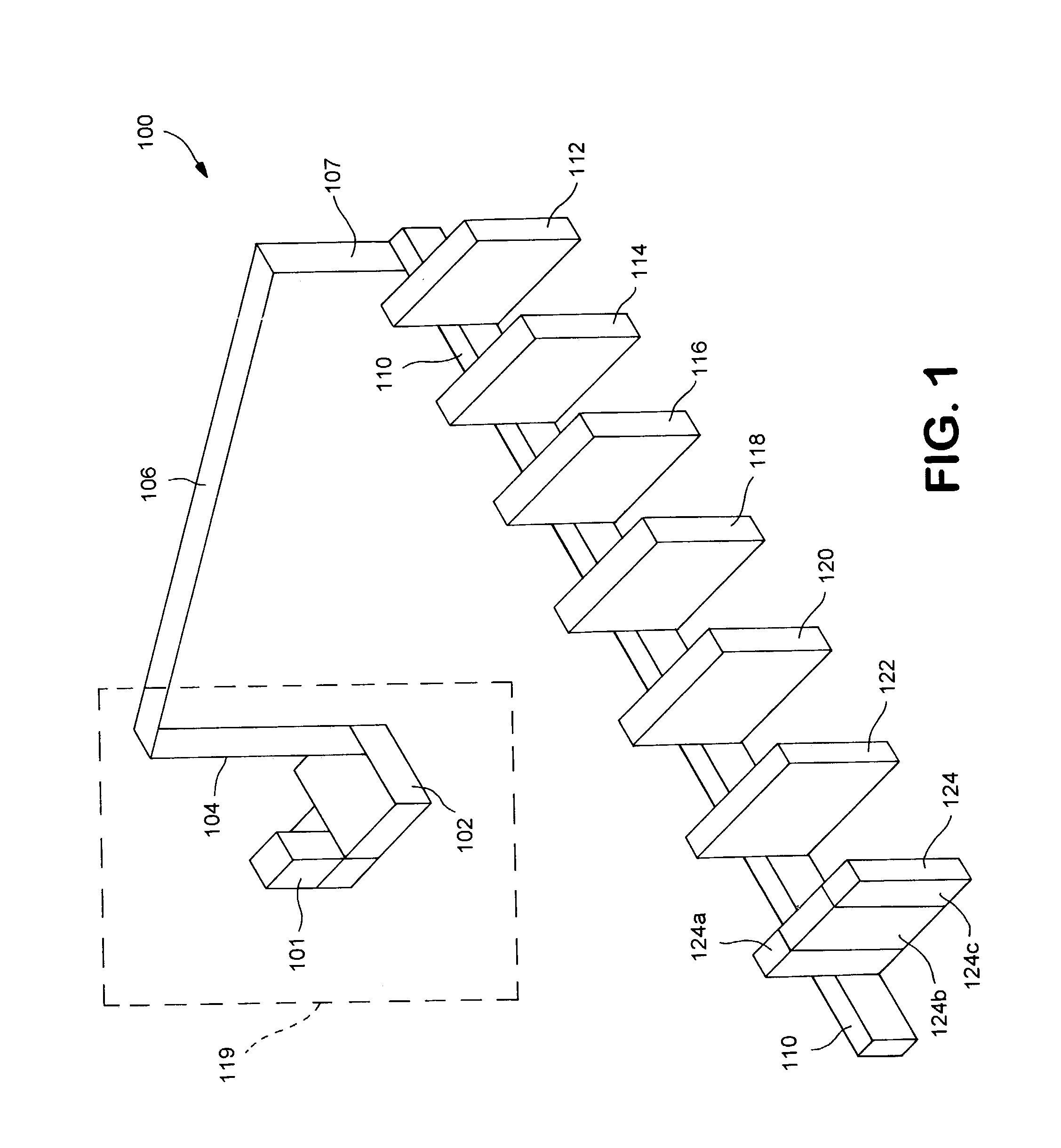
[0077]FIG. 1 shows a computer controlled process line 100 that is constructed in accordance with the present invention. The line is sometimes referred to as an Automated Processing System 100, and is controlled by a computer system 101 that keeps track of microtiter plates (MTPs) as they move along the process line. The computer system 101 also controls processing of the MTPs as the MTPs move through various process line modules and work stations. The computer system 101 can be used to specify particular modules that the MTPs will be directed to ...


PUM


Abstract

A sample preparation system provides an automated process that dispenses appropriate amounts of solid material into wells of a microtiter plate for mixing into a suspension. The system utilizes an array of hollow tubes that are lowered into a particle reservoir such that particle material is forced up into the tubes. During loading, solid plungers in the tubes are positioned a known distance from the open end of the tubes. When the particle material is to be dispensed, the plungers are lowered to push the particle material out of the tubes and into receiving wells of the microtiter plate. The plunger stroke and internal diameter of the tubes defines the dispensed volume of particle material.

Description

REFERENCE TO PRIORITY DOCUMENTS [0001]This claims priority from U.S. Provisional Application Ser. No. 60 / 348,745, filed Oct. 26, 2001, and U.S. Provisional Application Ser. No. 60 / 348,107, also filed Oct. 26, 2001. Both of those applications are incorporated herein by reference in their entirety.BACKGROUND OF THE INVENTION[0002]1. Field of the Invention[0003]The invention relates to process line systems and, more particularly, to the transfer of materials onto sample plates for laboratory analysis.[0004]2. Description of the Related Art[0005]Processing of biological materials often involves the automated transfer of sample materials onto reaction points for testing and analysis. Automated processing reduces the amount of time necessary to process large numbers of samples. For example, genetic sequencing efforts, such as the Human Genome project, involve processing of large numbers of samples, and have produced vast amounts of information for basic genetic research that have lead to ...

Claims


Application Information

Patent Timeline
IPC IPC(8): B65H5/00B01L3/02B65H3/08G01N1/10G05B21/00G01N33/53B01L7/00B01L7/02C12M1/00C40B60/14G01N1/00G01N1/28G01N35/00G01N35/02G01N35/10G01N37/00
CPCB01L3/0217B01L3/0244B01L7/52B01L9/50G01N35/1011G01N35/1065G01N35/1074B01J2219/00274Y10T436/2575B01J2219/00364B01J2219/00369B01J2219/00466B01J2219/005B01L3/0241B01L7/02B01L2200/022B01L2200/0657B01L2200/143B01L2300/0829B01L2300/185B01L2400/086C40B60/14G01N35/028G01N2035/00168G01N2035/00207G01N2035/00326G01N2035/00346G01N2035/00574B01J2219/00315B01L9/56
Inventor NANTHAKUMAR, ELIZABETHBACKES, JOSEFUNGER, SIEGFRIED
Owner AGENA BIOSCI
Why Eureka
Try Eureka