
Optical waveguide and method for producing the same

a technology of optical waveguides and optical fibers, applied in the direction of instruments, cladded optical fibres, liquid/solution decomposition chemical coatings, etc., can solve the problems of difficult to remove the uncured part of the photo-curable resin solution perfectly, the outer surface of the core becomes so bumpy, and the time required for optical waveguide production becomes longer. , to achieve the effect of high mutual solubility, low viscosity, and high viscosity

Inactive Publication Date: 2007-01-23
TOYODA GOSEI CO LTD
View PDF19 Cites 12 Cited by
  • Summary
  • Abstract
  • Description
  • Claims
  • Application Information

AI Technical Summary

Benefits of technology

The present invention provides a method for producing an optical waveguide with a high-refractive-index optical path portion and a low-refractive-index surface layer. The method involves using a mixture solution containing two photo-curable resin solutions with different curing mechanisms. The first solution is cured to form the optical path portion, while the second solution is cured to form the surface layer. The method includes steps of irradiating the mixture solution with light to form the optical path portion and diffusing the uncured parts of the first solution into the surface layer. The invention improves the efficiency of production and enhances the efficiency of the optical waveguide.

Problems solved by technology

Moreover, if a core is formed from only the high-refractive-index photo-curable resin solution and then a clad is formed on the outside of the core after cleaning, the time required for production of the optical waveguide becomes longer.
It is however not easy to remove uncured part of the photo-curable resin solution perfectly because the viscosity of the photo-curable resin solution is generally so high that uncured part of the photo-curable resin solution is deposited on the cured core portion by surface tension.
If the removal of uncured part of the photo-curable resin solution is imperfect, the following problem will occur.
First, if uncured part of the photo-curable resin solution is cured after a material for forming a clad is embedded while the uncured part of the photo-curable resin solution is deposited on the core portion, the outer surface of the core becomes so bumpy that a scattering loss increases.
In a complex portion such as a branch portion, a redundant loss such as a branch loss increases.
Incidentally, the possibility that uncured part of the photo-curable resin solution will remain in the branch portion is a significant issue even in the case where the viscosity of the photo-curable resin solution is low.
Even in the case where uncured part of the photo-curable resin solution is not deposited on the core, uncured part of the photo-curable resin solution may cause scattering of stray light or peeling of the clad from a housing or another optical component if the uncured part of the photo-curable resin solution remains in the inside of the housing or on the optical component.
As a result, the uncured part of the photo-curable resin solution may exert not a little bad influence on communication characteristic so that the influence leads to lowering of reliability.
First, the process of filling the vessel with a solvent, cleaning the vessel and drying the vessel increases.
The respective optical components, the core and the housing are destroyed easily because of peeling when the solvent penetrates into the interface between any two of the respective optical components, the core and the housing.
Penetration of the solvent into the core makes optical characteristic deteriorate.

Method used


Image

  • Optical waveguide and method for producing the same
  • Optical waveguide and method for producing the same
  • Optical waveguide and method for producing the same

Examples


first embodiment

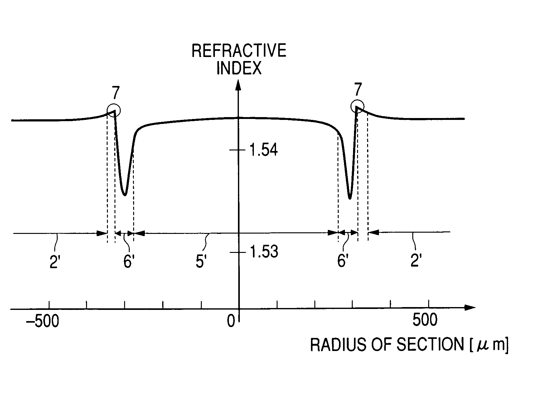
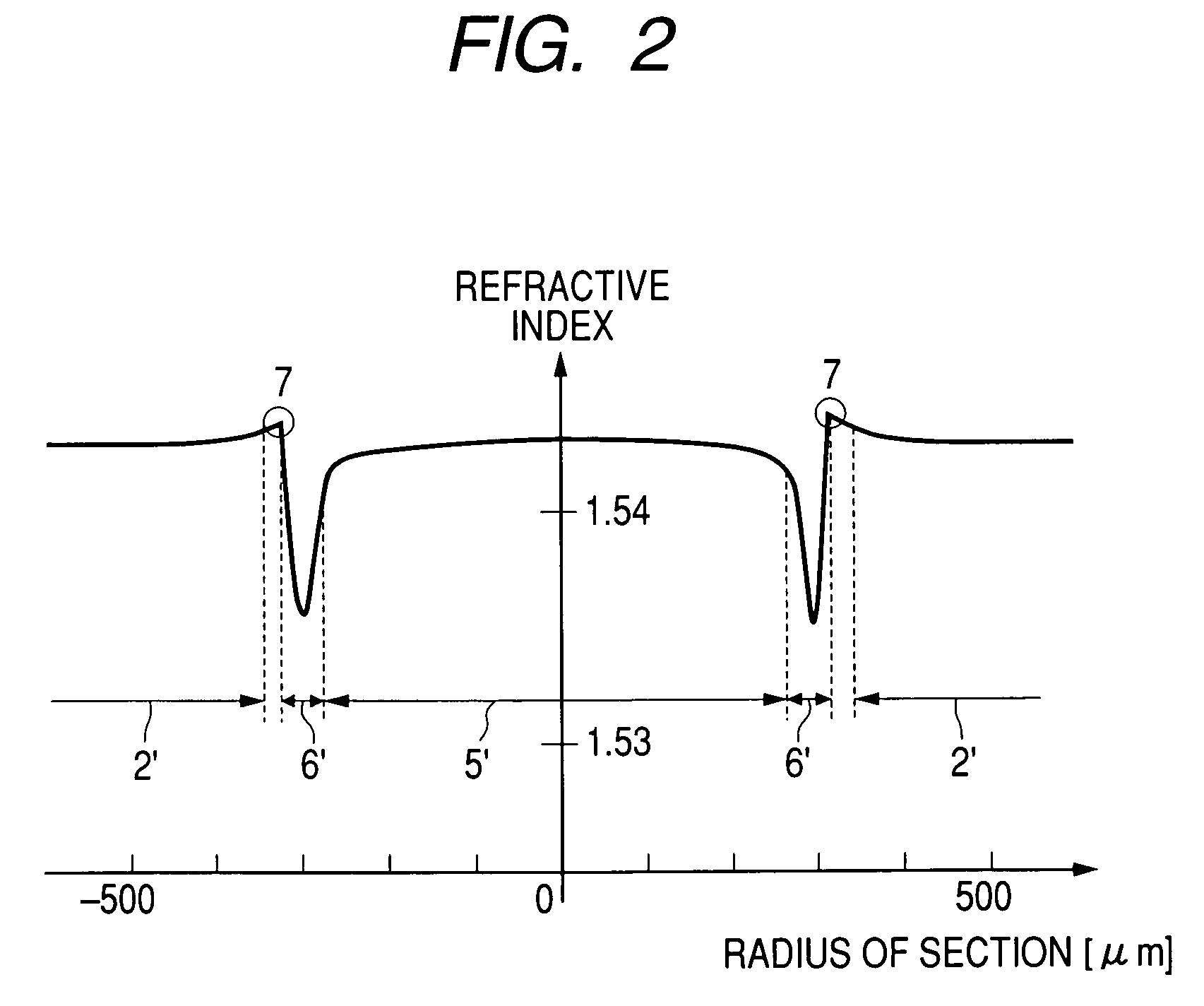
[0060]Sixty parts of radical polymerizable monomer (trade name “SR-454” made by Sartomer Company) with a refractive index of 1.471 and 0.5 parts of radical polymerization type visible-light photopolymerization initiator as the first photo-curable resin solution, and 40 parts of cationic polymerizable monomer (trade name “EPIKOTE 828” made by Japan Epoxy Resin Co., Ltd.) with a refractive index of 1.574 and 3.0 parts of cationic polymerization type ultraviolet-light photopolymerization initiator as the second photo-curable resin solution were mixed to prepare a mixture of the photo-curable resin solutions. The refractive index of the mixture solution was 1.514 before the mixture solution was cured. The refractive index of the cured of the mixture solution was 1.543 after the mixture solution was entirely cured by irradiation with ultraviolet rays. In Example 1, a mixture of the radical polymerizable monomer (trade name “SR-454”) with a refractive index of 1.471 and the radical polyme...

second embodiment

[0077]Each of core materials shown in Table 3 was used as a first curable resin solution capable of being cured by a light beam. A mixture containing 108 parts by weight of photo-curable OXT-221 made by Toagosei Co., Ltd. and 2 parts by weight of photo-curable UVR-6110 made by Union Carbide Corp. was used as a second curable resin solution. An optical waveguide was produced as follows. In Table 3, solubility parameter is simply abbreviated to “SP”. The term “SP” is hereinafter used as an abbreviation of “solubility parameter”. The viscosity of the second curable resin solution was 120 mPa·s. The SP of the second curable resin solution calculated on the basis of the SP 18.25 MPa1 / 2 of OXT-221 made by Toagosei Co., Ltd. and the SP 23.44 MPa1 / 2 of UVR-6110 made by Union Carbide Corp. was 19.28 MPa1 / 2. On this occasion, the solubility parameter was calculated in accordance with the Small's calculation method described in “Polymer Handbook 4th edition”, pp.682–685, John Wiley & Sons Inc....

third embodiment

[0083]An optical waveguide 110 was formed in the same manner as in the second embodiment except that a first curable resin solution 101 for forming a core as shown in Table 4 and a second curable resin solution 102 for forming a clad as shown in Table 4 were used. The transmission loss of the optical waveguide 110 was measured. Table 4 and FIGS. 8 and 9 show results of the measurement. FIG. 8 shows the relation between refractive index and specific gravity in five combinations of the first curable resin solution 101 and the second curable resin solution 102 before curing. In this embodiment, defencers OP-38, OP-40, OP-43, OP-44 and OP-47 made by Dainippon Ink and Chemicals, Inc. were used as fluorinated acrylic monomers. These are fluorine-substituted acrylic monomers. The defencer OP-38 is the largest in the amount of substituted fluorine. The defencers OP-40, OP-43, OP-44 and OP-47 are in descending order of the amount of substituted fluorine. For this reason, as the amount of sub...


PUM

PropertyMeasurementUnit
coefficient of viscosityaaaaaaaaaa
specific gravityaaaaaaaaaa

Abstract

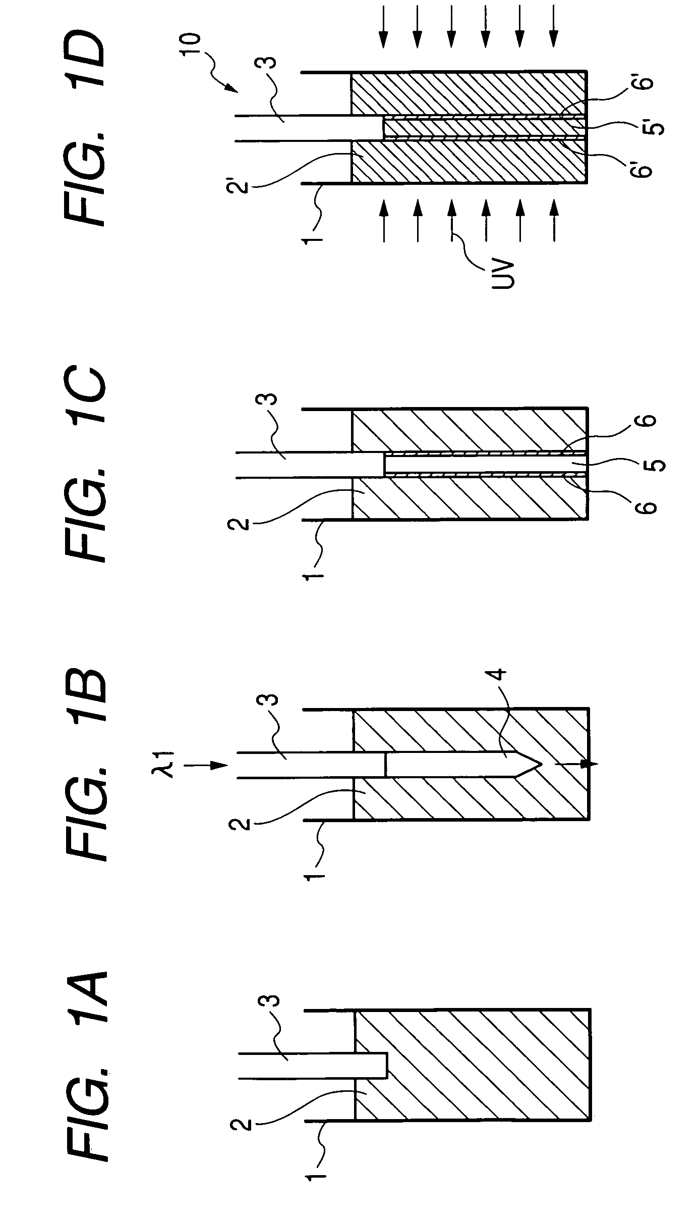
In the condition that an acrylic transparent vessel is filled with a curable resin solution capable of being cured by a light, a plastic optical fiber is immersed in the curable resin solution. A laser beam is applied on the curable resin solution through the plastic optical fiber. The curable resin solution is cured gradually by the laser beam applied on the curable resin solution, so that an axial core is formed. Then, the transparent vessel is left at rest for predetermined time, or uncured part of the curable resin solution is removed from the transparent vessel and the transparent vessel is then filled with another curable resin solution. Then, ultraviolet rays are applied on the transparent vessel from the outside of the transparent vessel to cure the residual uncured part of the curable resin solution.

Description

[0001]This application is based on Japanese Patent Applications No. 2003-290914 and 2003-290915, which are incorporated herein by reference.BACKGROUND OF THE INVENTION[0002]1. Field of the Invention[0003]The present invention relates to a method for producing an optical waveguide easily and inexpensively and a composition of material adapted for the method. The present invention also relates to a self-written optical waveguide having a columnar core made of the cured of a photo-curable resin solution. The term “photo-curable resin solution” used in the invention means a mixture of a photopolymerization initiator and at least one of photopolymerizable monomer, photopolymerizable macro-monomer and photopolymerizable oligomer.[0004]2. Description of the Related Art[0005]Attention has been paid to a technique of leading a light beam with a predetermined wavelength into a photo-curable resin solution to thereby use a self-focusing phenomenon to form an optical waveguide device. For examp...

Claims


Application Information

Patent Timeline
Patent Type & Authority Patents(United States)
IPC IPC(8): B05D5/06B29D11/00G02B6/10G02B6/138G02B6/30G02B6/42
CPCB29D11/00663G02B6/138G02B6/4246G02B6/4214G02B6/30
Inventor INUI, YUKITOSHIKAGAMI, MANABUKAWASAKI, AKARIYAMASHITA, TATSUYAYONEMURA, MASATOSHI
Owner TOYODA GOSEI CO LTD
Learn More