Organic-inorganic composite material and laminate, optical waveguide and light transmission structure comprising the same

a composite material and organic material technology, applied in the direction of natural mineral layered products, tyre parts, water-setting substance layered products, etc., can solve the problems of inability to meet the requirements of use, so as to achieve the effect of increasing the refractive index and reducing the refractive index

Inactive Publication Date: 2007-01-23
SANYO ELECTRIC CO LTD
View PDF8 Cites 23 Cited by
  • Summary
  • Abstract
  • Description
  • Claims
  • Application Information

AI Technical Summary

Benefits of technology

[0017]A first object of the present invention is to provide a production method capable of producing an organic-inorganic composite material excellent in optical transparency, as well as an organic-inorganic composite material obtainable by this method.
[0018]A second object of the present invention is to provide a light transmission structure having a light transmission layer with improved adhesion to a substrate.

Problems solved by technology

However, these materials are generally highly brittle and rigid, and their use may be limited because work or mechanical processing at a high temperature is necessary for working them into a desired shape.
However, the organic polymers are often inferior to the inorganic materials in heat resistance and chemical stability.
However, the production methods described in these literatures have a problem that organic-inorganic composite materials excellent in optical transparency cannot be obtained.
However, the methods proposed in the publications described above have a problem that the adhesion of the light transmission layer to the substrate cannot be sufficiently improved.

Method used


Image

  • Organic-inorganic composite material and laminate, optical waveguide and light transmission structure comprising the same
  • Organic-inorganic composite material and laminate, optical waveguide and light transmission structure comprising the same
  • Organic-inorganic composite material and laminate, optical waveguide and light transmission structure comprising the same

Examples


example 1

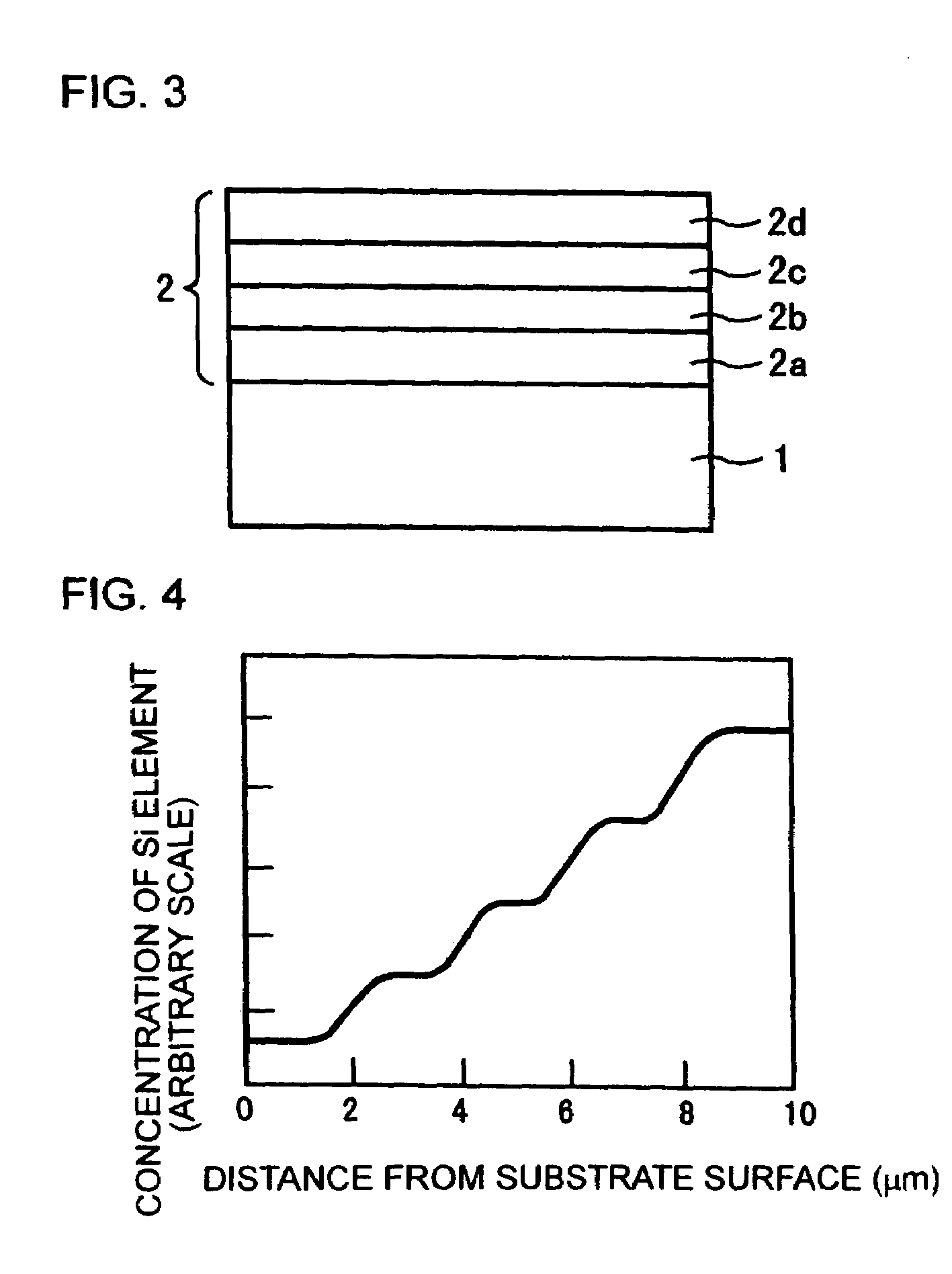
[0097]The coating solutions 5, 4, 3, 2 and 1 described above were applied in this order onto a quartz glass substrate, to form a laminate wherein 5 layers (films) made of the respective organic-inorganic composite materials were laminated. Each coating solution was applied by spin coating. It was predetermined for the thickness of each layer to be 2 μm after drying. The thickness of each layer was controlled by the number of revolutions of the substrate in the step of spin coating. Each coating solution was applied and then dried for 1 hour in an electric oven at about 110° C. Because 5 layers i.e. films were laminated, the test specimen was dried 5 times in total in the electric oven.

[0098]FIG. 4 is a graph showing the profile of concentration of Si element in the laminate formed in the manner described above. The concentration of Si element was measured by secondary ionization mass spectrometry (SIMS). In FIG. 4, the distance from the surface of the substrate is shown in the absci...

example 2

[0100]The coating solutions 5, 4, 3, 2 and 1 were applied in this order onto a quartz glass substrate (refractive index: 1.46) in the same manner as in Example 1, to form a laminate. In Example 2, however, the respective layers were formed so as to be 20, 10, 5, 3 and 22 μm in thickness, respectively.

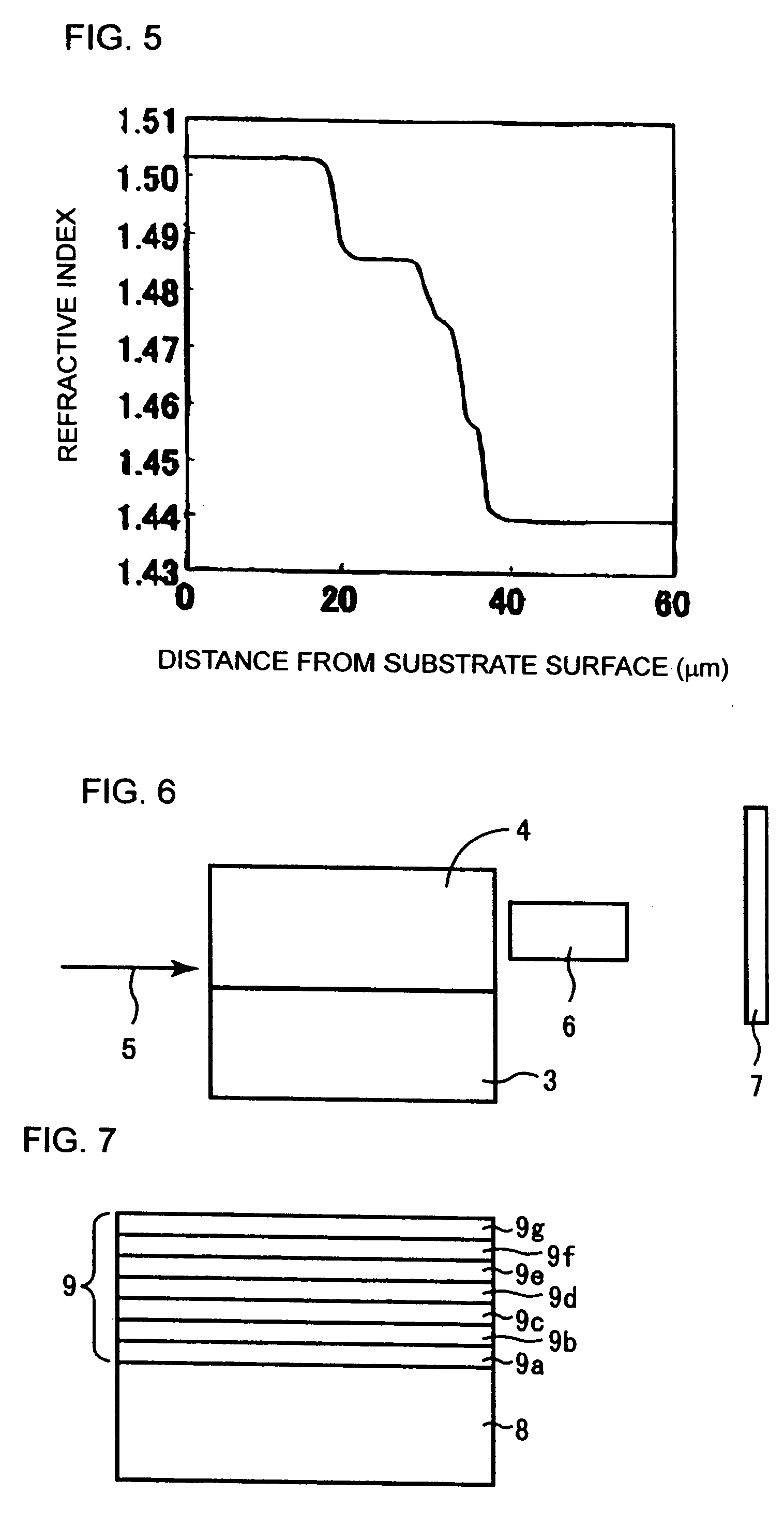
[0101]FIG. 5 is a graph showing the profile, in the direction of thickness, of the refractive index of the laminate in Example 2.

[0102]As shown in FIG. 5, this laminate is provided with a graded structure wherein the refractive index is gradually decreased from the substrate to the surface of the laminate.

[0103]As shown in FIG. 6, this laminate was used as a graded index-type planar optical waveguide. Referring to FIG. 6, laminate 4 is arranged on a quartz glass substrate 3. Laminate 4 is the laminate in Example 2. Laser light 5 was introduced into the end surface of a layer of low refractive index in laminate 4 near to the substrate 3. In the vicinity of the end surface of laminate 4 a...

example 3

[0107]The coating solutions 5, 4, 3, 2, 1, 2, 3, 4 and 5 were applied in this order onto a quartz glass substrate, to laminate thin films on the substrate. Each coating solution was applied and dried in the same manner as in Example 1. It was predetermined for the thickness of each layer to be 2 μm after drying. A laminate was formed by laminating 9 films in total.

[0108]FIG. 9 is a graph showing the profile of concentration of Si element in the direction of thickness in the laminate, as determined by SIMS. As shown in FIG. 9, the concentration of Si element is highest in the middle of the laminate, and the concentration of Si element is first increased and then decreased in the direction of thickness in the laminate. Accordingly, the refractive index is first decreased and then increased in the direction of thickness.

[0109]As shown in FIG. 9, those regions of about 1 μm in thickness wherein the concentration of Si element is almost constant have been formed apart by 1, 3, 5, 7, 9, 1...


PUM

PropertyMeasurementUnit
thicknessaaaaaaaaaa
domain sizesaaaaaaaaaa
transmittanceaaaaaaaaaa

Abstract

An organic-inorganic composite material is formed by polycondensating a metal alkoxide through hydrolysis until the unreacted metal alkoxide is reduced to 3 vol. % or less, and mixing it with an organic polymer. The composite material has a light transmittance of at least 90% per 10 μm material thickness for light of 600 to 1000 nm. The metal element content of the composite material is preferably 0.1 to 46 wt. %, more preferably 5 to 37 wt. %. By laminating layers of such organic-inorganic composite materials having respective different compositions, the resulting laminate has a concentration gradient wherein the metal element content increases or decreases monotonously, or increases and decreases in succession, from one side to the other side of the laminate. The resulting refractive index varies opposite the metal element content. The material can be used for an optical waveguide or a light transmission structure.

Description

CROSS-REFERENCE TO RELATED APPLICATION[0001]This application is a Divisional of U.S. application Ser. No. 10 / 346,340, filed Jan. 16, 2003, now U.S. Pat. No. 6,723,770 issued Apr. 20, 2004.BACKGROUND OF THE INVENTION[0002]1. Field of the Invention[0003]The present invention relates to an organic-inorganic composite material formed from an organic polymer and a metal alkoxide, and a laminate, an optical waveguide and a light transmission structure including the composite material.[0004]2. Related Art[0005]Inorganic materials such as metal and ceramics are excellent in heat resistance, mechanical strength, electrical properties, optical properties, chemical stability etc., and used widely in industry by utilizing these properties. However, these materials are generally highly brittle and rigid, and their use may be limited because work or mechanical processing at a high temperature is necessary for working them into a desired shape.[0006]On the other hand, organic polymers are excellen...

Claims


Application Information

Patent Timeline
Patent Type & Authority Patents(United States)
IPC IPC(8): C08J5/10C08G83/00C08K5/05C09D169/00
CPCC08G83/001C09D169/00C08K5/05Y10T428/265Y10T428/24917C08L2666/54C08L101/00
Inventor KURAMOTO, KEIICHIIZU, HIROAKIYAMANO, KOJIHIRANO, HITOSHI
Owner SANYO ELECTRIC CO LTD
Why Eureka
Try Eureka