Image enhancement system and method for night goggles

a technology of which is applied in the field of image enhancement system and eyeglasses, can solve the problems of preventing their effective use in applications, affecting the effect of eyeglasses, and significant constraints on the optical design of the system, so as to improve the visual acuity, and increase the field of view

Inactive Publication Date: 2007-01-30
NIGHT VISION CORP +1
View PDF10 Cites 17 Cited by
  • Summary
  • Abstract
  • Description
  • Claims
  • Application Information

AI Technical Summary

Benefits of technology

[0016]Thus, in one preferred embodiment, this invention presents an apparatus that significantly increases the field of view of night vision goggles utilizing four modular optical components to produce a panoramic field of vision. This invention also presents the advantage of providing an enlarged field of view with improved visual acuity and sufficient eye relief for a compact, lightweight, modular, binocular-like vision system.
[0017]In a further preferred embodiment, a panoramic night vision goggle is provided having enhanced low-light level sensitivity and resolution, as well as the ability to record the night sessions for later analyses, to transmit the video data of the night scene to a remote location in real time, and to insert or overlay the intensified image of the night scene with images from other sensors and/or data.
[0018]To achieve these objectives, a dichroic type narrow-band-pass filter is used as a beamsplitter positioned inside the eyepiece of the night vision goggle. This filter is combined with appropriately aligned polarizers and rotators to direct the intensified images of the night scene for recording, transmitting or further video processing. A miniature video cam

Problems solved by technology

Placing a night vision system on the head of a user places significant constraints upon the optical design of the system.
For example, goggles worn upon the head of a user must be both compact and light in weight because excessive weight or front-to-back length of the goggles can cause the goggles to exert large moments on the user's head causing severe instability problems and preventing their effective use in applications in which the user's head may be subjected to high gravitational or centrifugal loads.
Furthermore, in a wide field of view optical system, the focal length of the eyepiece optics must be shortened correlatively that of the wide angle objective for unity magnification; and, in night vision goggles, this results in insufficient

Method used


Image

  • Image enhancement system and method for night goggles
  • Image enhancement system and method for night goggles
  • Image enhancement system and method for night goggles

Examples


Embodiment Construction

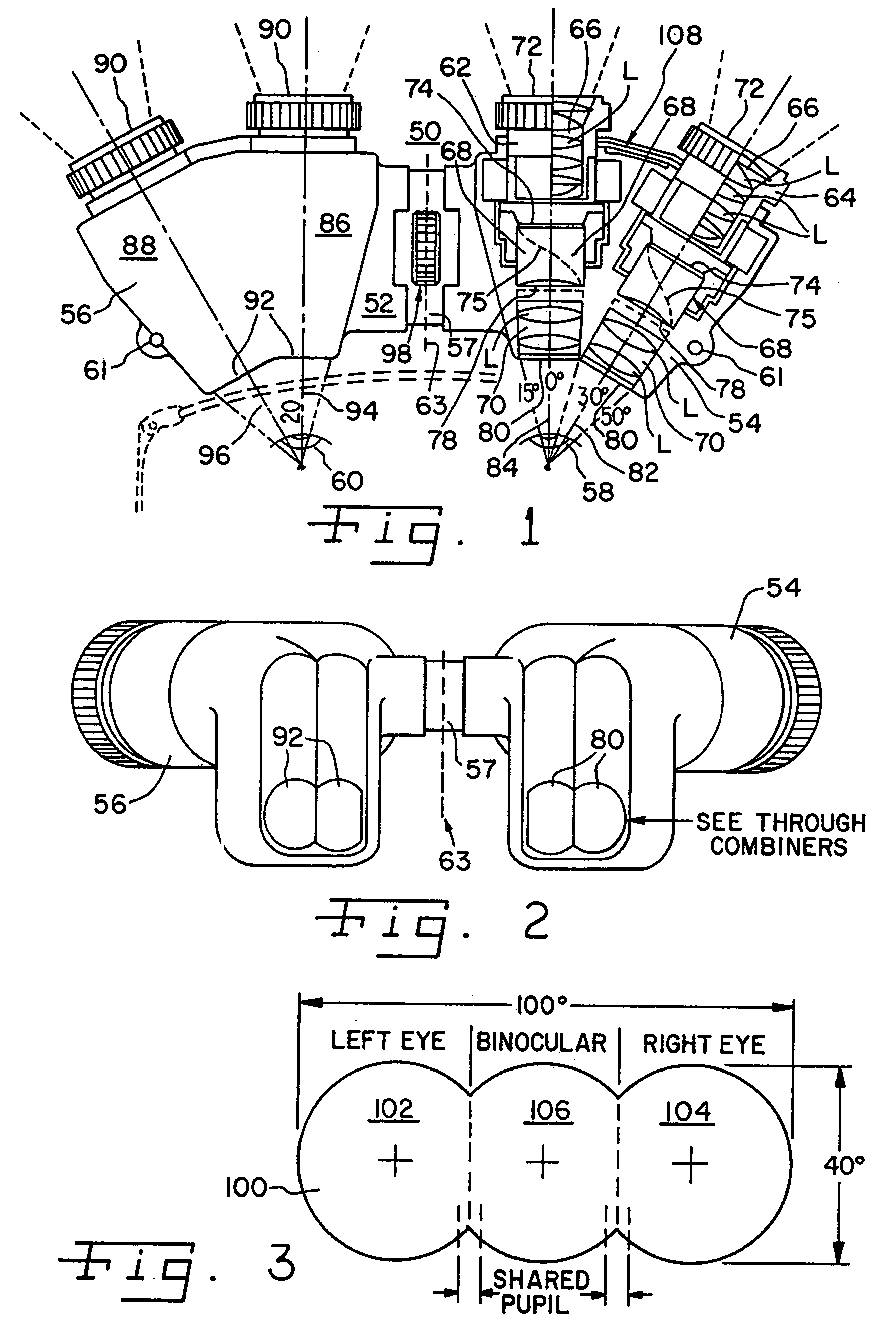
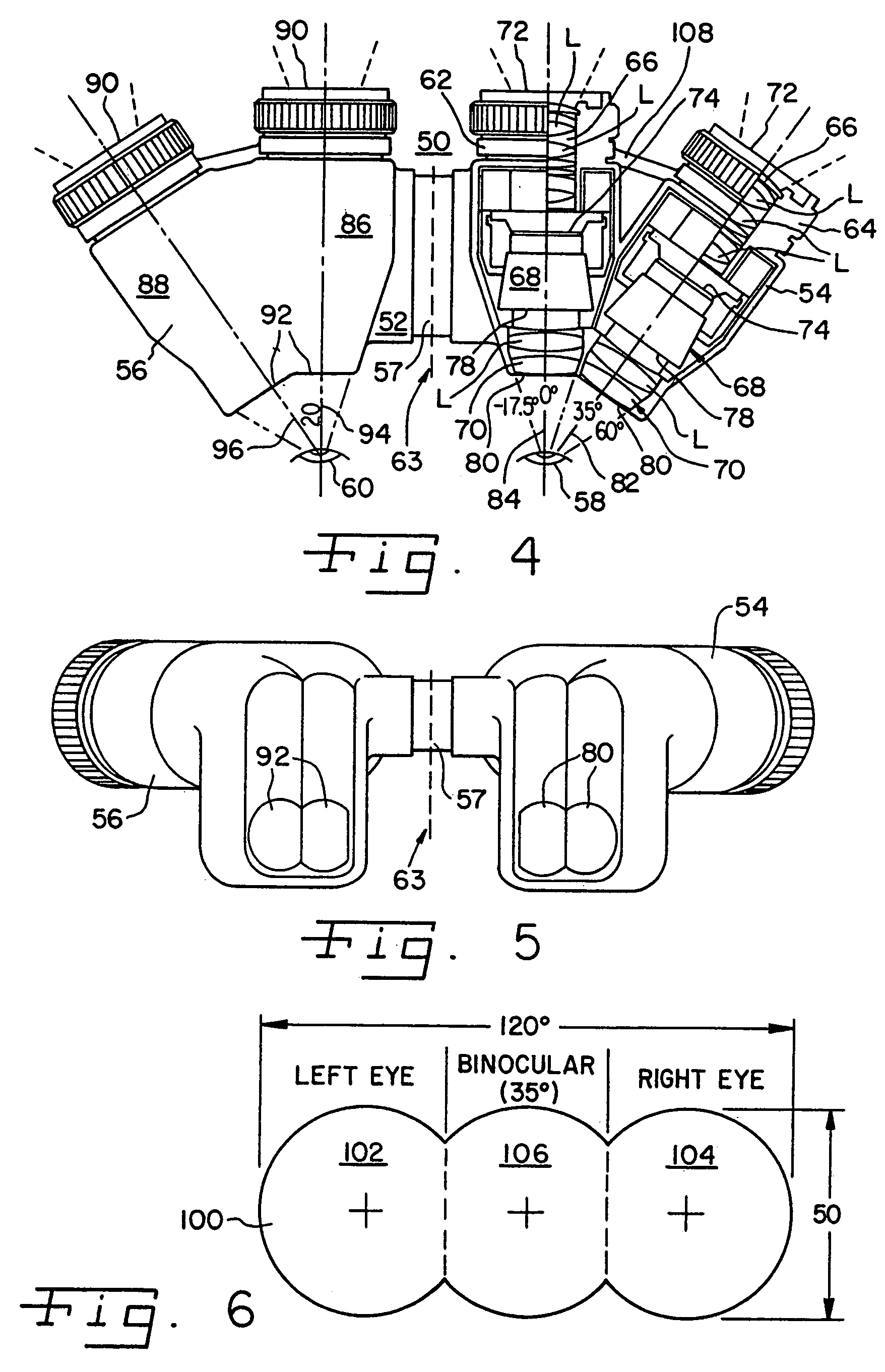
[0063]Several binocular-type-viewing systems according to the present invention are schematically shown in FIGS. 1–23, wherein like elements are identified by like numerals. A wide-angle lens group that provide a desired field of view of, for example, 40 degrees and can be of conventional design, such as disclosed in U.S. Pat. No. 5,416,315, the entire contents of which are incorporated herein by reference. The objective optical system 66 includes approximately 2 to 7 optical elements, such as plastic or glass lenses L, which have an effective focal length of approximately 21-mm, F / 1.2. The lenses L of the objective optical system are preferably spherical or aspherical in design.

[0064]The objective optical system 66 is designed to receive light from an object being viewed at the input end 72 and to transfer an image of the object to the input end or photocathode side 74 of the image intensifier tube 68.

[0065]The image intensifier tube 68 makes it possible for the observer to view an...


PUM


Abstract

A dichroic type narrow-band-pass filter is used as a beamsplitter inside a night vision goggle eyepiece. The filter is combined with appropriately aligned polarizers and liquid crystal type shutter rotators movable between a “P” orientation and an “S” orientation to transmit center band and side band wavelengths of the normal view or night scene for recording, transmitting or enhancing. In the enhanced low light level mode, the intensified visible image presented to the user comprises a 40 degree circular image with a 30 degree by 22.5 degree rectangular display insert.

Description

RELATED APPLICATION[0001]This application claims priority on a U.S. provisional patent application, U.S. Ser. No. 60 / 258,648, titled MODULAR PANORAMIC NIGHT VISION GOGGLES, filed Dec. 29, 2000.BACKGROUND OF THE INVENTION[0002]1. Field of the Invention[0003]This invention relates to an image enhancement system and method for night vision goggles that utilizes a spectral beamsplitter to enhance the low-light level sensitivity and resolution of the system, to enable the night missions to be recorded for later analyses, to transmit the video images of the night scene to a remote location in real time, and to insert or overlay the intensified image with images from other sensors and / or data.[0004]2. Discussion of Related Art[0005]Existing night vision systems have many applications in every day life. Perhaps the most well known use for night vision systems is by the military when performing nighttime maneuvers. The night vision systems permit vision under very low light conditions by con...

Claims


Application Information

Patent Timeline
IPC IPC(8): H01S1/00G02B26/00G02B23/12
CPCG02B23/125G02B23/12
Inventor FILIPOVICH, DANNYFIORE, JACKZIV, ROBERT O.UY, PHILIP
Owner NIGHT VISION CORP
Why Eureka
Try Eureka