Ink jet recording head and method for manufacturing the same

a recording head and jet technology, applied in the field of recording heads, can solve problems such as different shapes in the flow path of the jet, and achieve the effect of accurate formation

Inactive Publication Date: 2007-02-13
CANON KK
View PDF15 Cites 7 Cited by
  • Summary
  • Abstract
  • Description
  • Claims
  • Application Information

AI Technical Summary

Benefits of technology

[0010]In accordance with the method for manufacturing an ink jet recording head of the invention, the ink flow path can be accurately formed.
[0011]It is preferable that a positive resist layer (II) made of a photodegradation positive resist (ii) on the surface of the substrate, the photodegradation positive resist (ii) being different from the photodegradation positive resist (i) in a photosensitive wavelength range, and a method for manufacturing an ink jet recording head of the invention further includes (f) a process of removing a predetermined area of the positive resist layer (II) by a photolithographic process including an exposure step and a development step and forming the micro structure which becomes at least the ink flow path in the positive resist layer (II) in advance of the process (c). In accordance with the method for manufacturing an ink jet recording head of the invention, the convex ink flow path can be accurately formed. At this point, it is preferable that the photodegradation positive resist (ii) mainly includes polymethyl isopropenyl ketone.
[0018]In the ink jet recording head manufactured by the above-described ink jet recording head manufacturing method, the intended ink flow path can be accurately formed.

Problems solved by technology

However, sometimes a mutually soluble layer is formed between the pattern and a coating layer when the coating layer is formed on the pattern, which results in the ink flow path having the shape different from the intended shape.

Method used


Image

  • Ink jet recording head and method for manufacturing the same
  • Ink jet recording head and method for manufacturing the same
  • Ink jet recording head and method for manufacturing the same

Examples


first embodiment

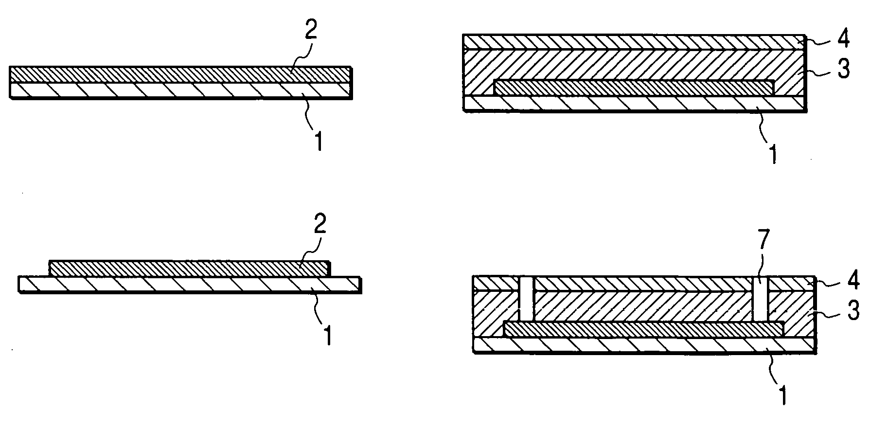
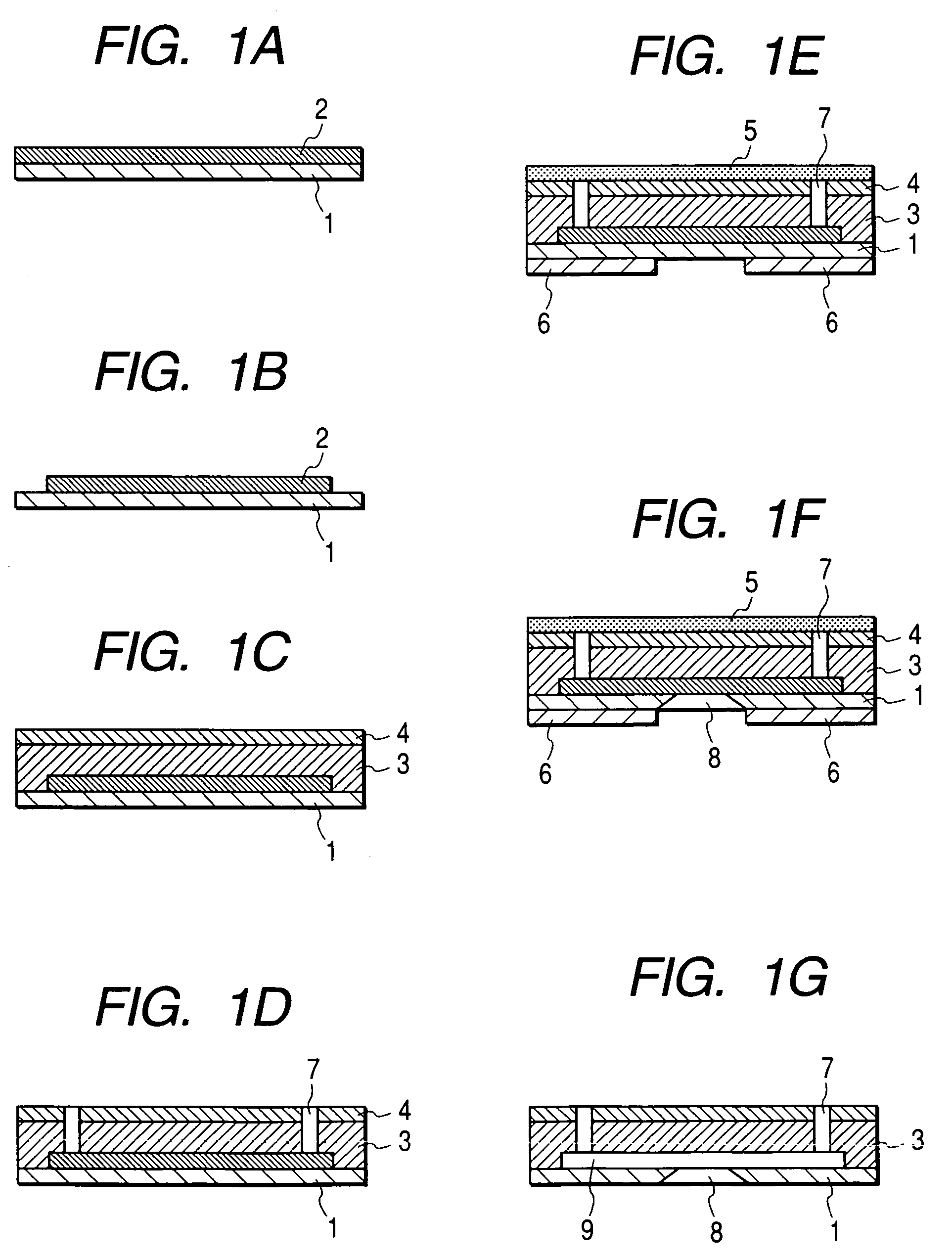
[0037]FIGS. 1A to 1G schematically show the method for manufacturing the ink jet recording head according to a first embodiment of the invention.

[0038]In the invention, a process (a) of forming a positive resist layer (I) made of a photodegradation positive resist (i) on the surface of the substrate having the energy generation element is first performed (FIG. 1A).

[0039]A substrate 1 made of glass, ceramic, metal, and the like is used as the substrate. The substrate 1 includes the energy generation element (not shown) for discharging the ink droplet. While an electrothermal energy generation element, a piezoelectric element, or the like can be used as the energy generation element, the energy generation element is not limited to the above-described elements. It is also possible to form the protection layer on the energy generation element for the purpose of release of impact in bubble foaming or reduction of damage from the ink.

[0040]Then, the photodegradation positive resist (i) is...

second embodiment

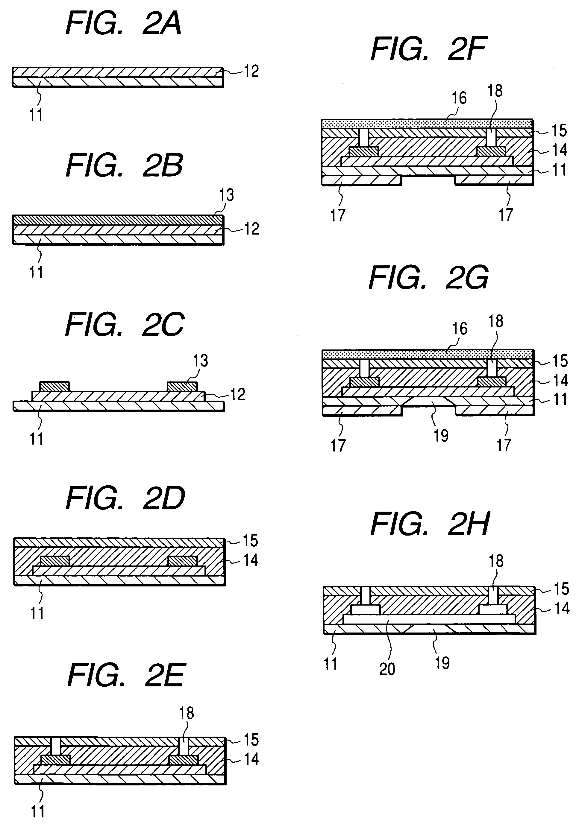
[0068]The method for manufacturing the ink jet recording head having a convex ink flow path will be described in detail as a second embodiment of the invention.

[0069]FIGS. 2A to 2H schematically show the method for manufacturing the ink jet recording head according to a second embodiment of the invention.

[0070]A positive resist layer (II) 12 made of a photodegradation positive resist (ii) which is different from the photodegradation positive resist (i) in the photosensitive wavelength range is formed on the surface of a substrate 11 (FIG. 2A).

[0071]As described above, since the photosensitive wavelength range of the photodegradation positive resist (i) including the glutarimide structure is around 250 nm, the resist made of polymethyl isopropenyl ketone (PMIPK), polyvinyl ketone, or the like which does not exhibit the photodegradation characteristics for the light near 250 nm but exhibits the photodegradation characteristics for the light near 290 nm can be used as the photodegradat...

example 1

[0081]In Example 1, the ink jet recording head was manufactured by the method for manufacturing an ink jet recording head shown by FIGS. 1A to 1G.

[0082]First the silicon substrate 1 was prepared. The energy generation element and a logic circuit for discharging the ink droplet were formed in the substrate 1.

[0083]Then, the positive resist layer (I) 2 made of the photodegradation positive resist (i) was formed in the laminar shape on the substrate 1. The photodegradation positive resist (i) used in Example 1 was obtained as follows:[0084]The photodegradation positive resist (i) (weight-average molecular weight: 85000) included the polymer in which 30 percent methyl methacrylate unit was glutarimidized by the reaction of polymethyl methacrylate and the mixed solution of 20 mass percent ammonia and 80 mass percent methyl amine.

[0085]Specifically, the resist solution in which the photodegradation positive resist (i) of about 19 mass percent in terms of solid content concentration was so...


PUM

PropertyMeasurementUnit
carbon numberaaaaaaaaaa
photosensitive wavelength rangeaaaaaaaaaa

Abstract

A method for manufacturing an ink jet recording head comprising: (a) a process of forming a positive resist layer (I) made of a photodegradation positive resist (i) on a surface of a substrate having an energy generation element; (b) a process of removing a predetermined area of the positive resist layer (I) by photolithography to form a micro structure which becomes at least an ink flow path; (c) a process of forming a coating resin layer on the surface of the substrate on which the micro structure has been formed; (d) a process of forming ink discharge ports in a portion where the coating resin layer covers the micro structure by photolithography; and (e) a process of removing the micro structure to form the ink flow path communicated with the ink discharge ports, wherein the photodegradation positive resist (i) includes a polymer having a glutarimide structure shown by the following chemical formula (1) in a molecule;wherein R1 designates a hydrogen atom or an alkyl group, an allyl group, or an aralkyl group which has the carbon number ranging from 1 to 20.

Description

BACKGROUND OF THE INVENTION[0001]1. Field of the Invention[0002]The present invention relates to an ink jet recording head, which performs recording by discharging ink to deposit to a recording medium, and a method for manufacturing the ink jet recording head.[0003]2. Related Background Art[0004]Generally the ink jet recording head includes an ink discharge port for discharging a micro ink droplet, an energy generation element for supplying energy to the ink droplet, and an ink flow path for supplying the ink. In the ink jet recording head, high-resolution and high-speed recording can be realized.[0005]The method disclosed in U.S. Pat. No. 5,478,606 can be cited as an example of the method for manufacturing the ink jet recording head. Further, in order to optimize a three-dimensional shape of an ink flow path, for example, U.S. Published Application No. 2003 / 011655 proposes the method in which an ink flow path pattern is formed in two layers by using positive resists having photodeg...

Claims


Application Information

Patent Timeline
Patent Type & Authority Patents(United States)
IPC IPC(8): B41J2/16
CPCB41J2/1603B41J2/1629B41J2/1631B41J2/1639B41J2/1645B41J2/1632Y10T29/49401
Inventor OKANO, AKIHIKOSHIBA, SHOJIISHIKURA, HIROE
Owner CANON KK
Why Eureka
Try Eureka