
Slotted electrode for high intensity discharge lamp

a discharge lamp and electrode technology, applied in the field of electric lamps, can solve the problems of difficult heat transfer of the head, degrading the steady-state affecting the operation of the lamp, so as to reduce the temperature of the electrode tip, reduce the evaporation of tungsten, and improve the maintenance effect of the lamp

Inactive Publication Date: 2007-02-13
OSRAM SYLVANIA INC
View PDF9 Cites 5 Cited by
  • Summary
  • Abstract
  • Description
  • Claims
  • Application Information

AI Technical Summary

Benefits of technology

The patent describes a way to make a high intensity discharge lamp with a recess on the electrode head. This recess helps to reduce the temperature of the electrode tip, which can prevent the evaporation of tungsten onto the inner wall of the lamp envelope during operation. By making the ratio of the head diameter to the head heat conductivity much larger than one, the patent aims to achieve higher maintenance of the lamp. The technical effect of this invention is to improve the performance and reliability of high intensity discharge lamps.

Problems solved by technology

Unfortunately, the massive head is difficult to heat initially and lamp starting may suffer.
If the wrapped head is too large, a high temperature spot mode arc attachment can occur that degrades the steady-state operation of the lamp, especially when no emitter material is used.
Coil wrapped electrodes can also have large performance variabilities, likely due to the variable heat connection between the rod and coil.
All of these effects can result in excessive electrode evaporation and sputtering.
However, thoria is felt to be environmentally undesirable.
Removal of thoria is especially difficult in general lighting applications using metal-halide lamps where the electrode must function well for starting and during steady-state alternating-current (AC) operation and the resulting evaporation.
The most significant is that coil-rod system is not well suited to large tip areas.
First, the poor thermal interfaces between coil windings and the coil and rod cannot transfer heat efficiently, particularly when the components are large.
The increased thermionic emission from the hotter regions increases the local heat flux and can result in undesirable spot arc attachment.
This mode of operation has very high, localized temperatures for tungsten electrodes without emitters, and leads to excessive evaporation of electrode material, and flickering of the arc
The second problem with large coils is slow starting.
The power deposition into the massive coil and rod is not large enough to rapidly raise the tip temperature to high enough values for good thermionic emission.
This is particularly troublesome without an emitter to reduce the glow-to-arc transition temperature.
However, the coil construction is complicated, requiring steps to sinter or melt tungsten powder between rod and coil and special coil winding steps to produce a graded coil diameter.
This emitter material is not chemically stable with many light-emitting metal-halide fills and evaporates much more rapidly than thoria, thus having limited use for long-life general lighting applications.
The emitter is also supplied as a pellet that must be enclosed in an electrode coil, adding to cost and complexity.
The use of non-thoriated emitters have the same disadvantages as Rademacher in metal-halide discharge lamps and the recess is used only to protect the emitter from direct contact by the discharge stream.
As stated in Daemen, the sintered form is not useful in many applications because of depletion by evaporation.
While this configuration improves starting maintenance, the manufacturing complexity and basic issues associated with a coil at the tip are not resolved.
The electrode in Yosiharu cannot reach the large optimal tip area because heating such a large electrode mass during the starting phase causes a long glow-to-arc transition over a large electrode surface area.
This results in excessive tungsten sputtering that blackens the lamp.
The design prevents overheating during the high-current instant-light requirement for automotive applications, but is not readily adaptable to higher-wattage general lighting situations where the glow-to-arc transition would be difficult.
Additionally, automotive HID lamps operate at very high pressures that reduce wall blackening and have lower life requirements than general lighting HID lamps.
However, unless special lamp and electrode conditions are met, the structure in Eggers has similar starting difficulties under conditions when tip area is large.
Furthermore, all of these disclosures do not disclose the special electrode, lamp, and ballast conditions necessary for achieving improved steady-state maintenance without spot attachment.

Method used


Image

  • Slotted electrode for high intensity discharge lamp
  • Slotted electrode for high intensity discharge lamp
  • Slotted electrode for high intensity discharge lamp

Examples


second embodiment

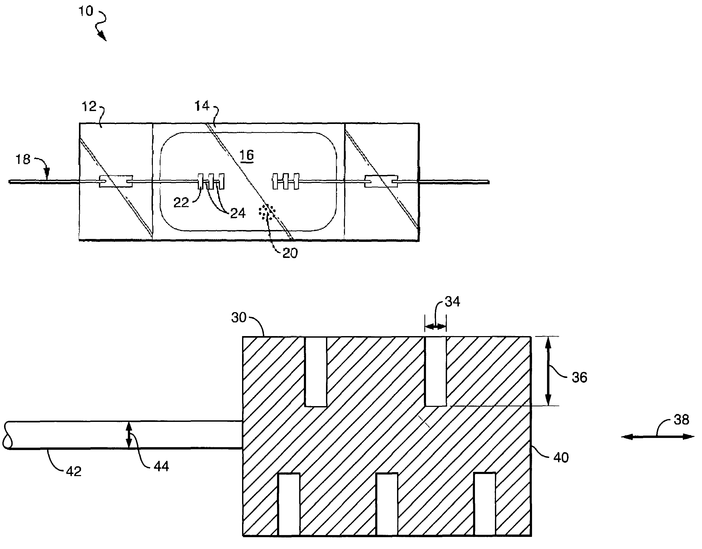
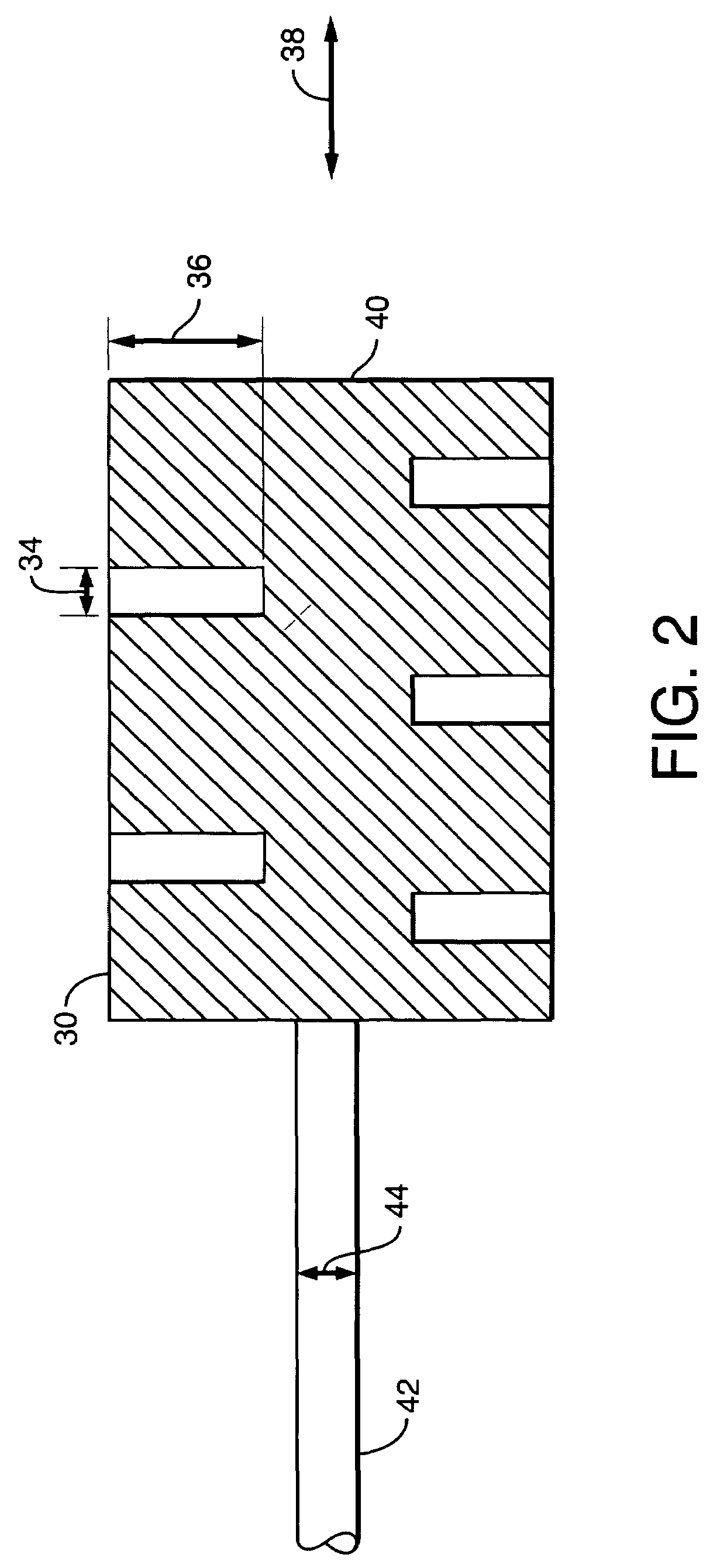
[0094]To test the steady-state performance of the recessed electrodes continuous life tests were performed on the slotted thoria-free HQI-T 400 W lamps with dh=1.5 mm and the thoriated control HQI lamp in Table 1. All lamps were burned in the horizontal orientation. HQI lamps with slotted thoria-free electrodes with head diameters dh=1.1 and 1.3 mm were also tested. To investigate the effect of the slots, identical HQI lamps with solid electrodes having the same dimensions as the slotted were additionally tested. All lamps were tested on 50 Hz choke ballasts operating at a nominal current of 3.5 A. After 1500 hours of operation, the following results on arc attachment were observed: All thoriated electrodes were found to run in spot mode attachment as often observed. Nearly all the solid thoria-free electrodes ran in a spot-mode or somewhat constricted arc attachment. All of the slotted (recessed) thoria-free electrodes ran in diffuse mode, consistent with previous observations of H...

third embodiment

[0095]In a third embodiment, shown in FIG. 9, the recesses are replaced by one or more hollow regions on the top of the tip body to achieve a similar hollow cathode effect. Mechanical or laser drilling can form the hollow regions. The hollow regions must satisfy the requirements for a hollow cathode discharge during starting. In the case of argon buffer gas, the diameter of the hollow dh and depth of the hollow lh must satisfy the conditions,

70hp<1200 Pa-cm  Equation 6a

The recess depth D must be large enough to contain sputtered tungsten within the recess and to provide enough current:

D>dg.  Equation 6b

fourth embodiment

[0096]In a fourth embodiment shown in FIG. 10, such hollow recess regions can be on the front side of the tip body, either alone or with hollow regions on the top of the tip body. The electrode 70 may be formed as a solid body with an inner stem 72 supporting a head 74 at the innermost end of the electrode 70. The head 74 may include a flat end face 76. Formed in face 76 may be one or more recesses such as a hole, slot, slit or groove. The recess may be an axially extending bore 80. Bore 80 has a least spanning distance (diameter) 82 and a depth 84. The diameter 82 is greater than the maximum electron ionization mean free path but less than twice the minimum cathode fall plus one negative glow distance, throughout the glow discharge phase of starting and for the chosen fill gas composition and pressure. The depth 84 is preferably greater than the spanning distance 82. It is understood there may be a plurality of such bores on the front face 76, and that grooves, slots, and similar o...


PUM


Abstract

Operation of an HID lamp may be improved by forming a glow generating recess on an exterior side the electrode. The lamp may be of standard construction with a light transmissive lamp envelope having a wall defining an enclosed volume. At least one electrode assembly is extended in a sealed fashion from the exterior of the lamp through the lamp envelope wall to be exposed at an inner end of the electrode assembly to the enclosed volume. A metal halide lamp fill is enclosed with an inert fill gas. The inner end of the electrode is formed with a recess having a least spanning dimension S and a recess depth of D where S is greater the electron ionization mean free path but less than twice the cathode fall plus negative glow distances, throughout the glow discharge phase of starting, for the chosen fill gas composition and pressure (cold).

Description

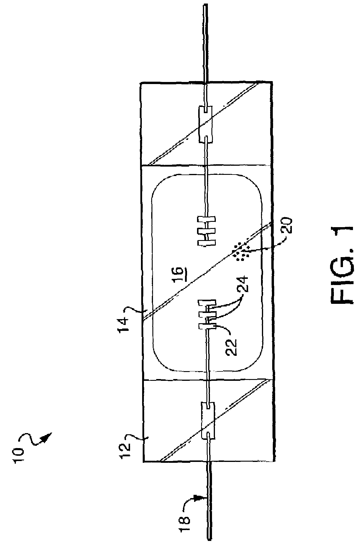
FIELD OF THE INVENTION[0001]The invention relates to electric lamps and particularly to high intensity discharge lamps. More particularly the invention is concerned with electrodes for use in high intensity discharge lamps.DESCRIPTION OF THE RELATED ART INCLUDING INFORMATION DISCLOSED UNDER 37 CFR 1.97 AND 1.98BACKGROUND OF THE INVENTION[0002]It is common for an arc discharge lamp to have an electrode with a massive head formed on the interior end of a rod. For example, many metal halide high-intensity discharge lamps use an electrode with a straight tungsten rod wrapped with a coil to form the head. During operation the wrapped head provides a larger area from which thermionic electrons are emitted, resulting in a more durable electrode that operates at lower temperatures. Unfortunately, the massive head is difficult to heat initially and lamp starting may suffer. If the wrapped head is too large, a high temperature spot mode arc attachment can occur that degrades the steady-state ...

Claims


Application Information

Patent Timeline
Patent Type & Authority Patents(United States)
IPC IPC(8): H01J17/18
CPCH01J61/0732H01J61/827H01J61/09
Inventor LENEF, ALAN L.ADLER, HELMARBUDINGER, A. BOWMANLI, YAN MING
Owner OSRAM SYLVANIA INC
Learn More