Cooling apparatus and method, and exposure apparatus having the cooling apparatus

a technology of exposure apparatus and cooling apparatus, which is applied in the field of cooling apparatus and method, can solve the problems of difficult use of refraction elements or lenses for visible light and ultraviolet light, affecting the efficiency of exposure apparatus, and reducing the deformation of optical elements

Inactive Publication Date: 2007-03-20
CANON KK
View PDF15 Cites 7 Cited by
  • Summary
  • Abstract
  • Description
  • Claims
  • Application Information

AI Technical Summary

Benefits of technology

[0012]Accordingly, it is an exemplary object of the present invention to provide a cooling apparatus and method, and an exposure apparatus having the cooling apparatus adjustment method and apparatus for adjusting

Problems solved by technology

However, the lithography using the ultraviolet light has the limit to satisfy the rapidly promoting fine processing of a semiconductor device, and a reduction projection optical system using extreme ultraviolet (“EUV”) light with a wavelength of 10 to 15 nm shorter than that of the ultraviolet (referred to as an “EUV exposure apparatus” hereinafter) has been developed to efficiently transfer a very fine circuit pattern of 0.1 μm or less.
The light absorption in a material remarkably increases as the wavelength of the exposure light becomes shorter, and it is difficult to use a refraction element or lens for visible light and ultraviolet light.
T

Method used


Image

  • Cooling apparatus and method, and exposure apparatus having the cooling apparatus
  • Cooling apparatus and method, and exposure apparatus having the cooling apparatus
  • Cooling apparatus and method, and exposure apparatus having the cooling apparatus

Examples


Embodiment Construction

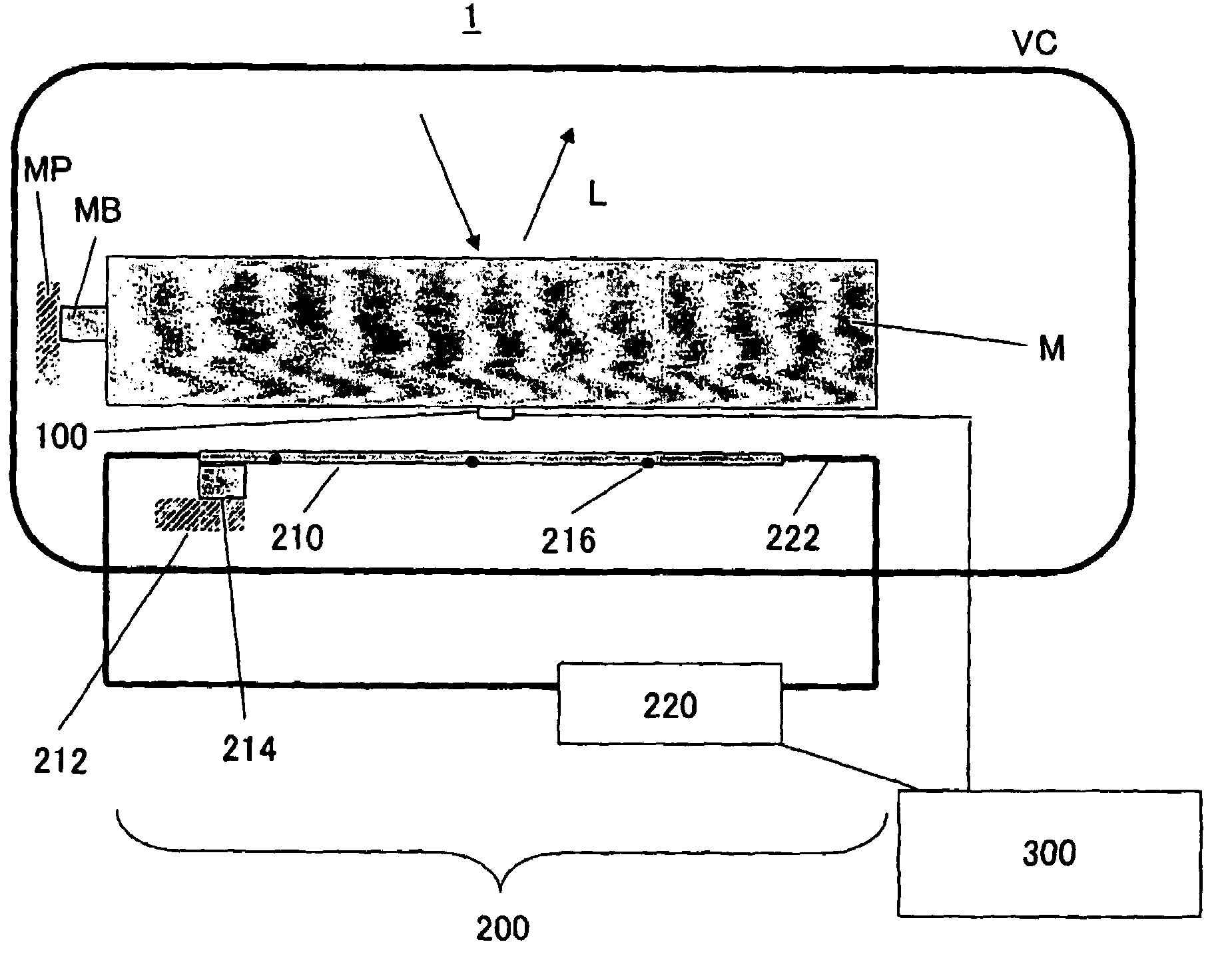
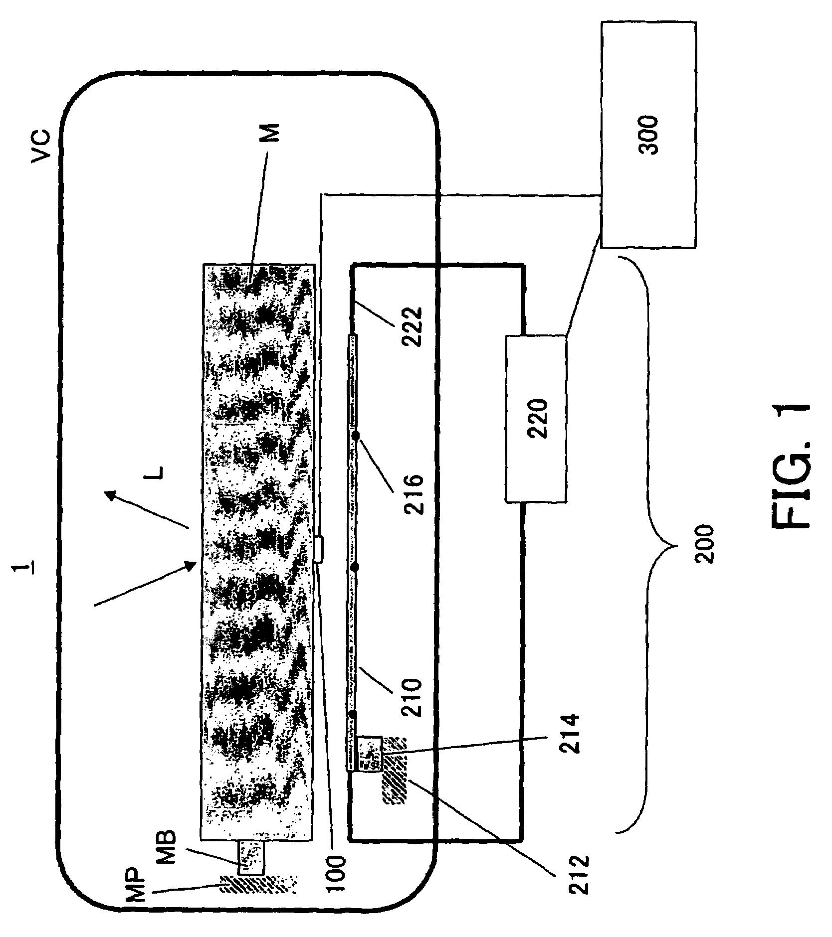
[0031]With reference to accompanying drawings, a description will now be given of a cooling apparatus and method as one embodiment according to the present invention. In each figure, the same reference numeral denotes the same element, and a duplicate description will be omitted. Here, FIG. 1 is a schematic structure of a cooling apparatus 1 of one aspect according to the present invention.

[0032]The cooling apparatus 1 is one for cooling an optical element M provided in a vacuum chamber VC. The vacuum chamber VC is maintained to be high vacuum, for example, about 1×10⁶ [Pa] by a vacuum pump (not shown) so that a reaction between the residual gas component in the exposure optical path, such as polymer organic gas, and EUV light may not contaminate a mirror surface and lower its reflectance. The optical element M is located at a predetermined position via an optical-element support member MV that is supported by an optical-element support stool MP in the vacuum chamber VC, and images ...


PUM


Abstract

A cooling apparatus for cooling an optical element provided in a vacuum atmosphere includes a radiational cooling part, arranged apart from the optical element, for cooling the optical element by radiation heat transfer, and a controller for controlling temperature of the radiation cooling part.

Description

[0001]This application claims a benefit of priority based on Japanese Patent Applications No. 2002-222911, filed on Jul. 31, 2002, which is hereby incorporated by reference herein in its entirety as if fully set forth herein.BACKGROUND OF THE INVENTION[0002]The present invention relates generally to cooling apparatuses, and more particularly to a cooling apparatus for cooling an optical element used in an exposure apparatus that exposes an object, such as a single crystal substrate for a semiconductor wafer (plate or ball), and a glass plate (wafer) for a liquid crystal display (LCD). The present invention is particularly suitable, for example, for an exposure apparatus that uses ultraviolet light and extreme ultraviolet (“EUV”) light as a light source for exposure.[0003]A reduction projection exposure apparatus has been conventionally employed which uses a projection optical system to project a circuit pattern formed on a mask (reticle) onto a wafer, etc. to transfer the circuit pa...

Claims


Application Information

Patent Timeline
IPC IPC(8): F25B21/02F25D19/00G03F7/20H01L35/00
CPCF25B21/02H01L35/00G03F7/70233G03F7/70891F25D19/00F25B2321/0212H10N10/00
Inventor HARA, SHINICHI
Owner CANON KK
Why Eureka
Try Eureka