Variable speed fan motor control for forced air heating/cooling system

a technology of forced air heating and cooling system, which is applied in the direction of temperatue control, starter details, dynamo-electric motor/converter starter, etc., can solve the problems of unsatisfactory noise and maximize the capture of residuals, and achieve the effect of easy adaptation

Inactive Publication Date: 2007-03-20
HOFFMAN CONTROLS CORP
View PDF22 Cites 17 Cited by
  • Summary
  • Abstract
  • Description
  • Claims
  • Application Information

AI Technical Summary

Benefits of technology

[0009]In another embodiment, three sensors are disposed in the ductwork including the return air sensor which is disposed upstream with regard to the direction of airflow from an air heater heat exchanger, a heat sensing sensor which is disposed downstream of the air heater heat exchanger and a third sensor which is disposed downstream of an air cooling heat exchanger, such as an evaporator coil, for example. In this way a more versatile control system is provided and more accurate sensing of temperature is obtained, depending on the operating condition of the system, heating versus cooling.
[0010]The control systems of the present invention advantageously reduce energy consumption of conventional forced air heating and cooling systems, improve recovery of residual heating / cooling effect in conventional forced air heating / cooling systems, minimize stratification of air in the airflow circuit and the space being heated or cooled and reduce cold or hot air drafts during operation of the heating / cooling system. Moreover, by substantially continuously varying the fan or blower drive motor speed during startup and shutdown, noise associated with fan or blower operation is reduced and the circulation of air at a temperature other than normally sensed or preferred by occupants of an indoor space being heated or cooled is also reduced.

Problems solved by technology

However, changing motor speed abruptly from a deenergized or shutoff state to full speed usually generates unpleasant noise, does not preclude stratification of air in the system ductwork or in the space being heated or cooled, nor does such operation maximize the capture of residual heat / cooling effect of the system heat exchange equipment.
Again, this type of control system does not minimize the stratification of warm or cold air in the ductwork or the space being heated or cooled nor does such a system maximize the capture of residual heating / cooling effect.

Method used


Image

  • Variable speed fan motor control for forced air heating/cooling system
  • Variable speed fan motor control for forced air heating/cooling system
  • Variable speed fan motor control for forced air heating/cooling system

Examples


Embodiment Construction

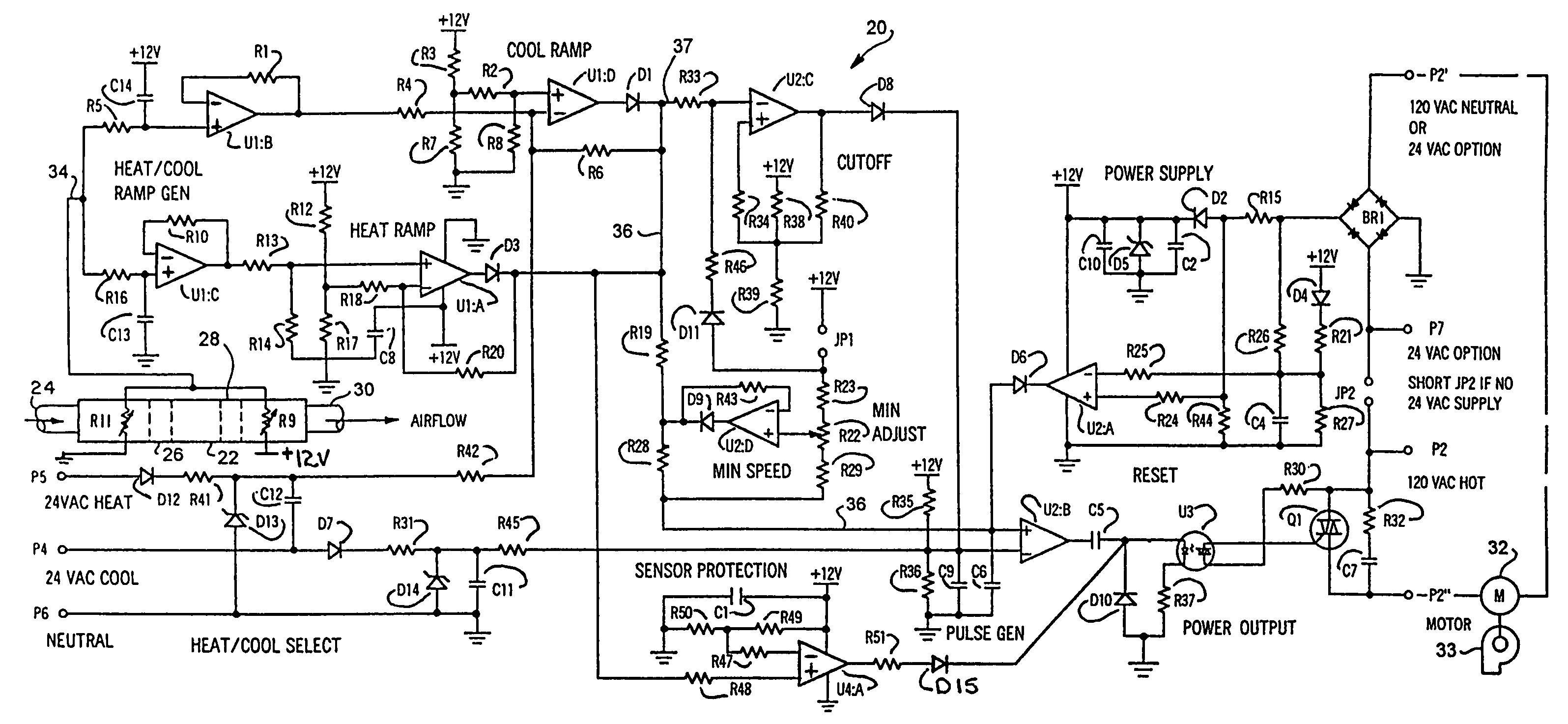
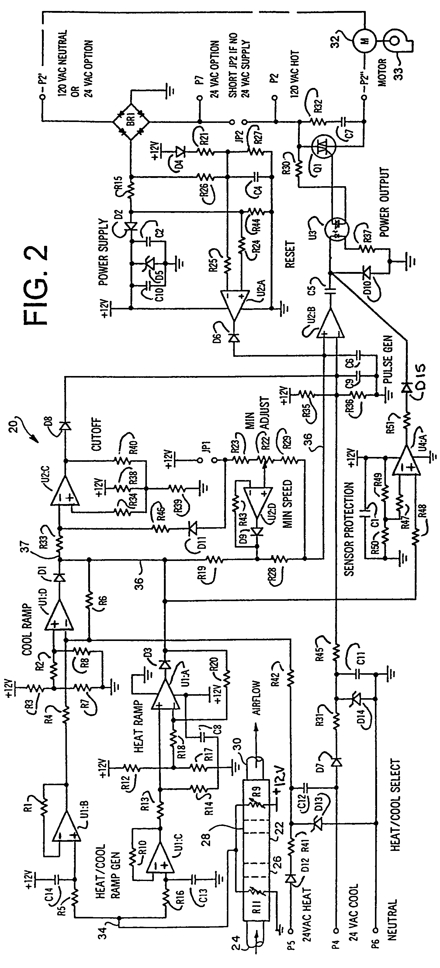
[0016]In the description which follows like elements are marked throughout the specification and drawing with the same reference numerals, respectively. Conventional elements are shown in somewhat generalized or schematic form in the interest of clarity and conciseness.

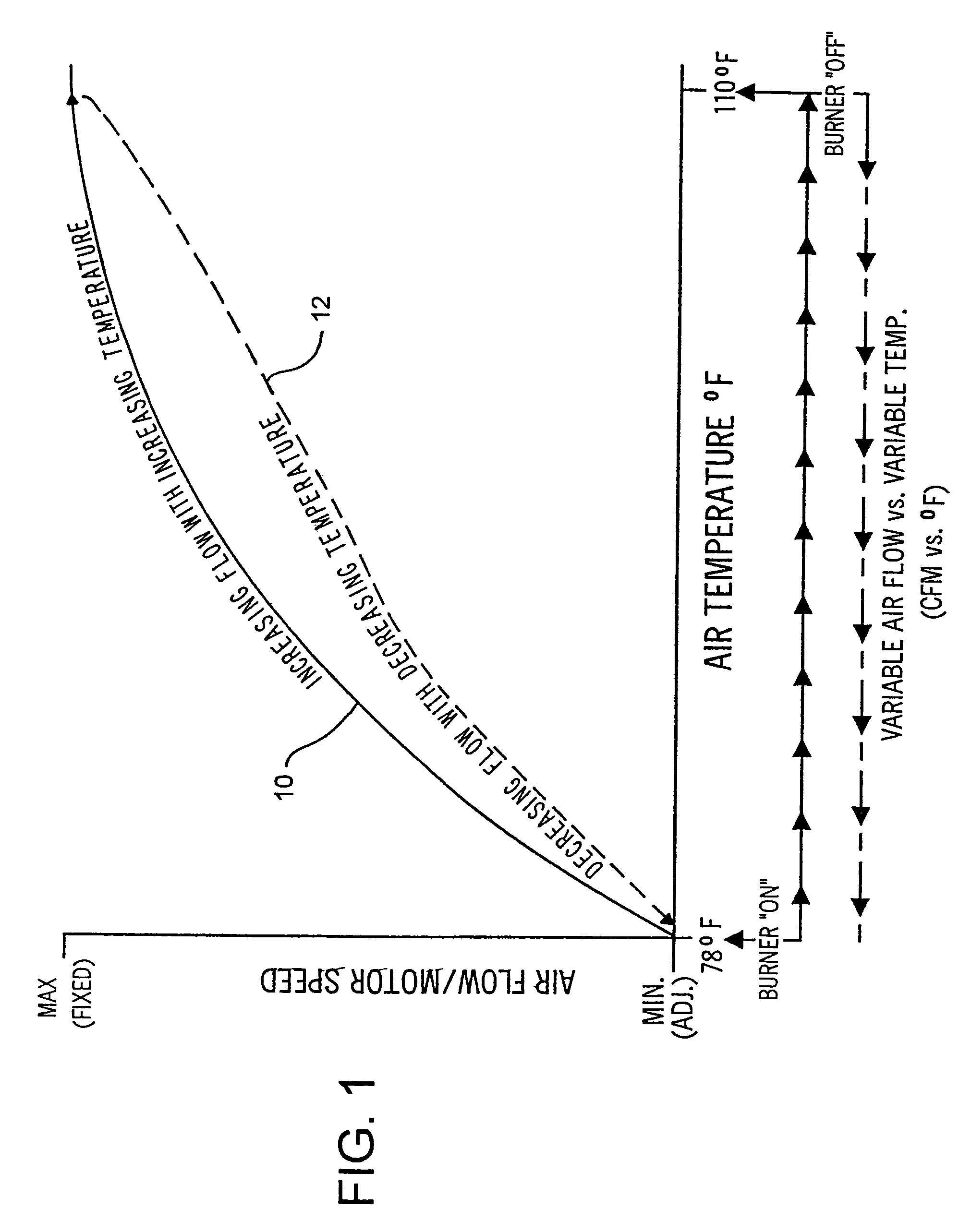
[0017]Referring to FIG. 1, the diagram illustrates a preferred change in motor speed and airflow rate through a conventional forced air heating / cooling system when the system thermostat senses the need for heating, for example, at a temperature setpoint of 78° F. in the space being heated. When the temperature sensed by the conventional system temperature sensor or thermostat drops below the setpoint of 78° F., for example, the furnace or heater turns on and the control system of the invention energizes the blower or fan drive motor at a minimum speed. When the air temperature sensed in the system ductwork increases, primarily at a location just downstream of the heater heat exchanger, as compared with the temperature...


PUM


Abstract

A fan motor speed control system for controlling the fan motor speed of an air conditioning system includes a power output circuit including a power triac which is turned on and off by an opto-isolator connected to a pulse generator circuit for varying an AC voltage waveform imposed on the fan motor. The pulse generator circuit is connected to heating and cooling ramp circuits and a minimum speed circuit to provide a variable voltage signal imposed on the pulse generator circuit corresponding to the temperature difference sensed by a return air sensor and a heating or cooling sensor or by separate heating and cooling sensors disposed adjacent respective heating and cooling heat exchangers of the air conditioning system. An adjustable minimum speed circuit and a cutoff circuit are provided to control motor minimum speed or motor shutoff when a predetermined minimum speed is reached to prevent motor bearing failure or overheating. Sensor protection circuits in the control system operate to drive the motor to full speed if any of the temperature sensors experience an open or short circuit condition. The control system circuit maximizes air conditioning system efficiency by capturing additional heating or cooling effect, reduces noise associated with motor startup and shutdown, and reduces rapid change in the sensed temperature in the air conditioned space during motor startup and shutdown.

Description

CROSS REFERENCE TO RELATED APPLICATION[0001]This application is a continuation of U.S. patent application Ser. No. 09 / 629,328, filed Aug. 1, 2000, now U.S. Pat. No. 6,695,046, issued Feb. 24, 2004, which is a continuation-in-part of U.S. patent application Ser. No. 09 / 570,880, filed May 15, 2000, now U.S. Pat. No. 6,684,944, issued Feb. 3, 2004 which is a continuation of U.S. patent application Ser. No. 08 / 801,560, filed Feb. 18, 1997, now U.S. Pat. No. 6,070,660, issued on Jun. 6, 2000.FIELD OF THE INVENTION[0002]The present invention pertains to a control system for continuously varying the speed of a fan drive motor for a forced air indoor space heating / cooling system during startup and after shutdown of a heating / cooling cycle.BACKGROUND OF THE INVENTION[0003]Conventional controls for forced air heating and cooling systems often provide for delayed startup of the fan drive motor at a single operating speed and delayed shutdown of the drive motor from a single operating speed aft...

Claims


Application Information

Patent Timeline
Patent Type & Authority Patents(United States)
IPC IPC(8): F25B29/00F23N5/20F04D27/00F24F11/00
CPCF04D27/00F24F11/0079Y10S236/09Y02B30/746F24F11/77Y02B30/70
Inventor BYRNES, HOWARD P.BOWMAN, WALTER WILLIAM
Owner HOFFMAN CONTROLS CORP
Why Eureka
Try Eureka