Inertial GPS navigation system with modified kalman filter

a navigation system and filter technology, applied in the field of gps receivers, can solve the problems of satellite signals detrimental to use, gps receivers may not calculate position information, gps satellites may become unavailable to gps receivers, etc., to speed up gps satellite signal re-acquisition and associated ambiguity resolution operations, and eliminate the effect of system dynamics

Active Publication Date: 2007-03-20
NOVATEL INC
View PDF8 Cites 114 Cited by
  • Summary
  • Abstract
  • Description
  • Claims
  • Application Information

AI Technical Summary

Benefits of technology

[0014]The GPS observable may be delta phase measurements, and the other observables may be, for example, wheel pick-offs (or counts of wheel revolutions) that are used to calculate along track differences, and so forth. The inclusion of the measurements in the filter together with the current and the previous position related information essentially eliminates the effect of system dynamics from the system model. A position difference can thus be formed that is directly observable by the phase difference or along track difference measured between the previous and current time epochs. Further, the delta phase measurements can be incorporated in the INS filter without having to maintain GPS carrier ambiguity states.
[0015]The INS sub-system and the GPS sub-system share GPS and INS position and covariance information. The receiver time tags the INS and any other non-GPS measurement data with GPS time, and then uses the INS and GPS filters to produce INS and GPS position information that is synchronized in time. The GPS/INS receiver utilizes GPS position and associated covariance information and the GPS and/or other observables in the updating of the INS filter. The INS filter, in turn, provides updated system error information that is used to propagate inertial current p

Problems solved by technology

If the GPS receiver does not, at any given time, receive the signals from a minimum number of satellites, the GPS receiver is unable to calculate position information.
The GPS satellites may become unavailable to the GPS receiver for various periods of time in, for example, urban environments, when the GPS receiver travels under a bridge, through a tunnel, or through what is referred to in the literature as an “urban canyon,” in which buildings block the signals or produce excessively large multipath signals that make the satellite signals detrimental to use for position calculations.
In addition, operating the GPS r

Method used


Image

  • Inertial GPS navigation system with modified kalman filter
  • Inertial GPS navigation system with modified kalman filter
  • Inertial GPS navigation system with modified kalman filter

Examples


Embodiment Construction

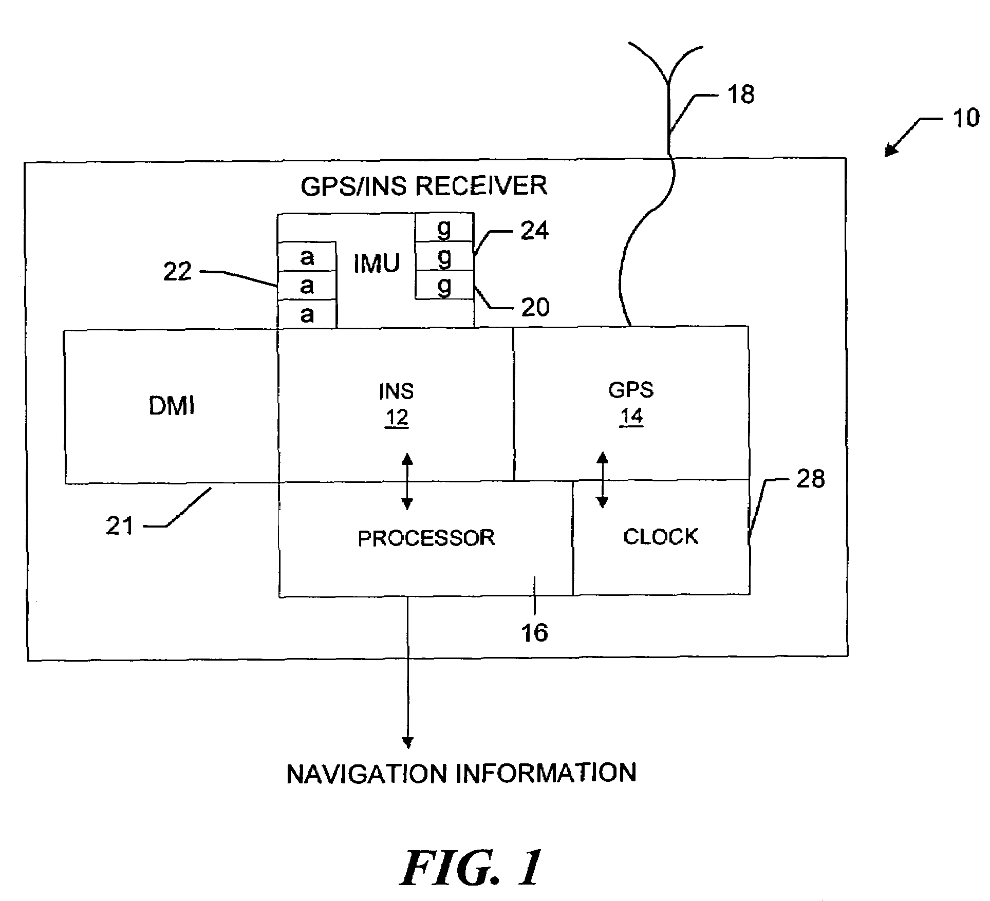
[0022]Referring now to FIG. 1, a GPS / INS receiver 10 includes an INS sub-system 12 and a GPS sub-system 14 that operate under the control of a processor 16, to calculate GPS position and INS position, velocity and attitude information. The GPS subsystem processes the satellite signals received over an antenna 18. The INS sub-system receives measurements from an inertial measuring unit (“IMU”) 20 that reads data from orthogonally positioned accelerometers 22 and gyroscopes 24. In addition, the INS sub-system may receive data from a distance measurement indicator (“DMI”) 21, such as a wheel pick-off (not shown). The data from the IMU and, as appropriate, from the DMI, are time tagged with the GPS time maintained by a GPS-time clock 28, as discussed in more detail below, such that the two sub-systems can reliably interchange position-related information that is synchronized in time. The two subsystems operate together, through software integration in the processor 16, to provide positi...


PUM


Abstract

An inertial (“INS”)/GPS receiver includes an INS sub-system which incorporates, into a modified Kalman filter, GPS observables and/or other observables that span previous and current times. The INS filter utilizes the observables to update position information relating to both the current and the previous times, and to propagate the current position, velocity and attitude related information. The GPS observable may be delta phase measurements, and the other observables may be, for example, wheel pick-offs (or counts of wheel revolutions) that are used to calculate along track differences, and so forth. The inclusion of the measurements in the filter together with the current and the previous position related information essentially eliminates the effect of system dynamics from the system model. A position difference can thus be formed that is directly observable by the phase difference or along track difference measured between the previous and current time epochs. Further, the delta phase measurements can be incorporated in the INS filter without having to maintain GPS carrier ambiguity states. The INS sub-system and the GPS sub-system share GPS and INS position and covariance information. The receiver time tags the INS and any other non-GPS measurement data with GPS time, and then uses the INS and GPS filters to produce INS and GPS position information that is synchronized in time. The GPS/INS receiver utilizes GPS position and associated covariance information and the GPS and/or other observables in the updating of the INS filter. The INS filter, in turn, provides updated system error information that is used to propagate inertial current position, velocity and attitude information. Further, the receiver utilizes the inertial position, velocity and covariance information in the GPS filters to speed up GPS satellite signal re-acquisition and associated ambiguity resolution operations

Description

CROSS-REFERENCE TO RELATED APPLICATIONS[0001]The present application claims the benefit of U.S. Provisional Patent Application Ser. No. 60 / 441,612, which was filed on Jan. 21, 2003, by Thomas John Ford et al. for a MEMS INERTIAL ON RTK GPS RECEIVER and is hereby incorporated by reference.BACKGROUND OF THE INVENTION[0002]1. Field of the Invention[0003]The invention relates generally to GPS receivers and, more particularly, to GPS receivers that incorporate inertial systems.[0004]2. Background Information[0005]A global positioning system (GPS) receiver requires signals from a number of GPS satellites in order to accurately calculate its position. The GPS receiver acquires and tracks signals consisting of carrier, pseudo random codes and modulated data from various satellites. The receiver correlates locally-generated codes with the codes received from the respective satellites to derive timing information relating the receiver time relative to the local generation of code chips to the...

Claims


Application Information

Patent Timeline
IPC IPC(8): G01S5/14G01S19/49G01C21/16G01P15/02G01S1/00G01S5/02G01S19/26
CPCG01C21/165G01S19/49G01S19/26G01C21/188
Inventor FORD, THOMAS JOHNHAMILTON, JASONBOBYE, MICHAEL
Owner NOVATEL INC
Why Eureka
Try Eureka