
Spin valve sensor having a nonmagnetic enhancement layer adjacent an ultra thin free layer

a non-magnetic enhancement and sensor technology, applied in the field of spin valve sensors, can solve the problems of reducing the performance of the spin valve, and ultimately the data density, and achieve the effect of effective bias point control

Inactive Publication Date: 2007-03-27
WESTERN DIGITAL TECH INC
View PDF21 Cites 147 Cited by
  • Summary
  • Abstract
  • Description
  • Claims
  • Application Information

AI Technical Summary

Benefits of technology

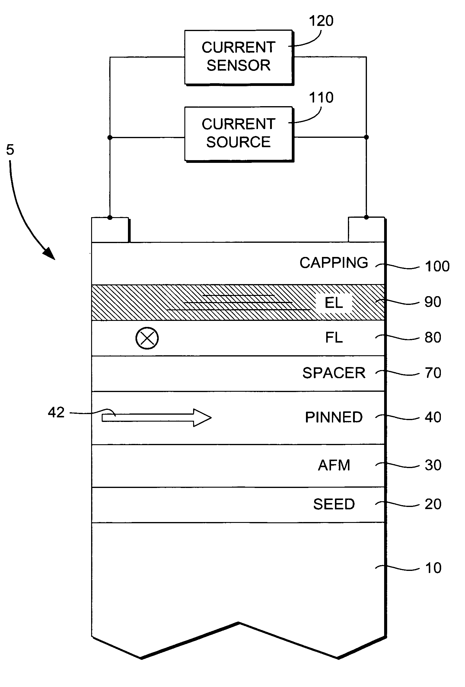
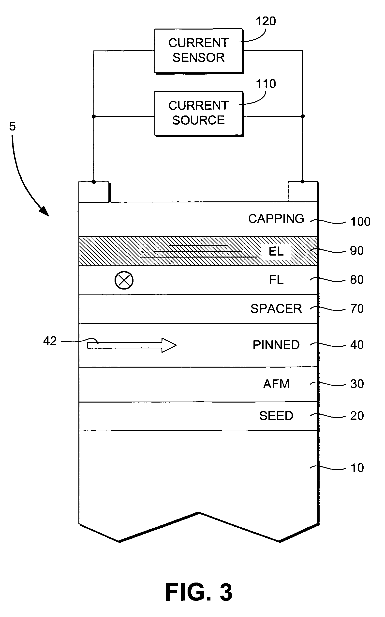
[0011]The preferred embodiment of the present invention provides a spin valve device having a non-magnetic enhancement layer adjacent to a free layer. The enhancement layer of the preferred embodiment allows the free layer to be formed ultra thin so that the thickness of the free layer is less than the mean free path of conduction electrons through the free layer. In a typical embodiment, this allows the thickness of the free layer to be reduced to below about 50 Angstroms without the reduction in GMR effect normally associated with such thicknesses. In addition, the introduction of the enhancement layer provides for effective bias point control in spin valve sensor design by shifting the sensor current density distribution.
[0012]In the preferred embodiment, the enhancement layer provides an improved conduction path for electrons as the thickness of the free layer is made ultra thin. With the preferred embodiment, the material of the enhancement layer is selected so that its electronic properties are reasonably matched with the adjacent free layer to allow electrons to continue conducting through the enhancement layer. It is preferred to select a material with sufficiently low resistance to allow more electrons to travel in their spin state before they encounter scattering sites while not creating a low resistance shunt path which competes with GMR gains derived from the improved conduction path length. It is also preferred to select the material of the enhancement layer so that it provides the desired electrostatic discharge, current flow, heating, or other properties. Moreover, material selection also is dependent on enhancement layer thickness because the amount of improvement in GMR ratio is dependent on material type and thickness. As such, different embodiments of the present invention may employ different materials for the enhancement layer to improve GMR effect in ultra thin free layer spin valves.
[0013]The enhancement layer of the present invention may employ several different types of non-magnetic materials to improve GMR effect. In a presently preferred embodiment, Cu is used as the enhancement layer material. In addition to improving the GMR, the Cu enhancement layer provides low sheet resistance, and also provides favorable thermal stability and magnetostriction properties with an adjacent CoFe free layer.
[0014]In another embodiment NiFeCr is used as the enhancement layer material. In addition to improving the GMR, the NiFeCr enhancement layer provides low sheet resistance, and also provides favorable thermal stability and magnetostriction properties with an adjacent NiFe free layer. It also provides a good seed texture, which is particularly desirable in top spin valve embodiments. In another embodiment, in addition to improving the GMR ratio, the NiFeCr enhancement layer adjacent a CoFe free layer also improves the CoFe free layer coercivity.
[0015]With the preferred embodiments of the present invention, because the free layer is made ultra thin and the enhancement layer is formed of a non-magnetic material, less magnetic field is required from the magnetic media to align the free layer, thus allowing for improved data density.

Problems solved by technology

One result of reducing the thickness of the free layer, however, is that it also reduces the performance of the spin valve.
Thus, in conventional spin valves, spin valve performance, and ultimately data density, is limited by free layer thickness.

Method used


Image

  • Spin valve sensor having a nonmagnetic enhancement layer adjacent an ultra thin free layer
  • Spin valve sensor having a nonmagnetic enhancement layer adjacent an ultra thin free layer
  • Spin valve sensor having a nonmagnetic enhancement layer adjacent an ultra thin free layer

Examples


Embodiment Construction

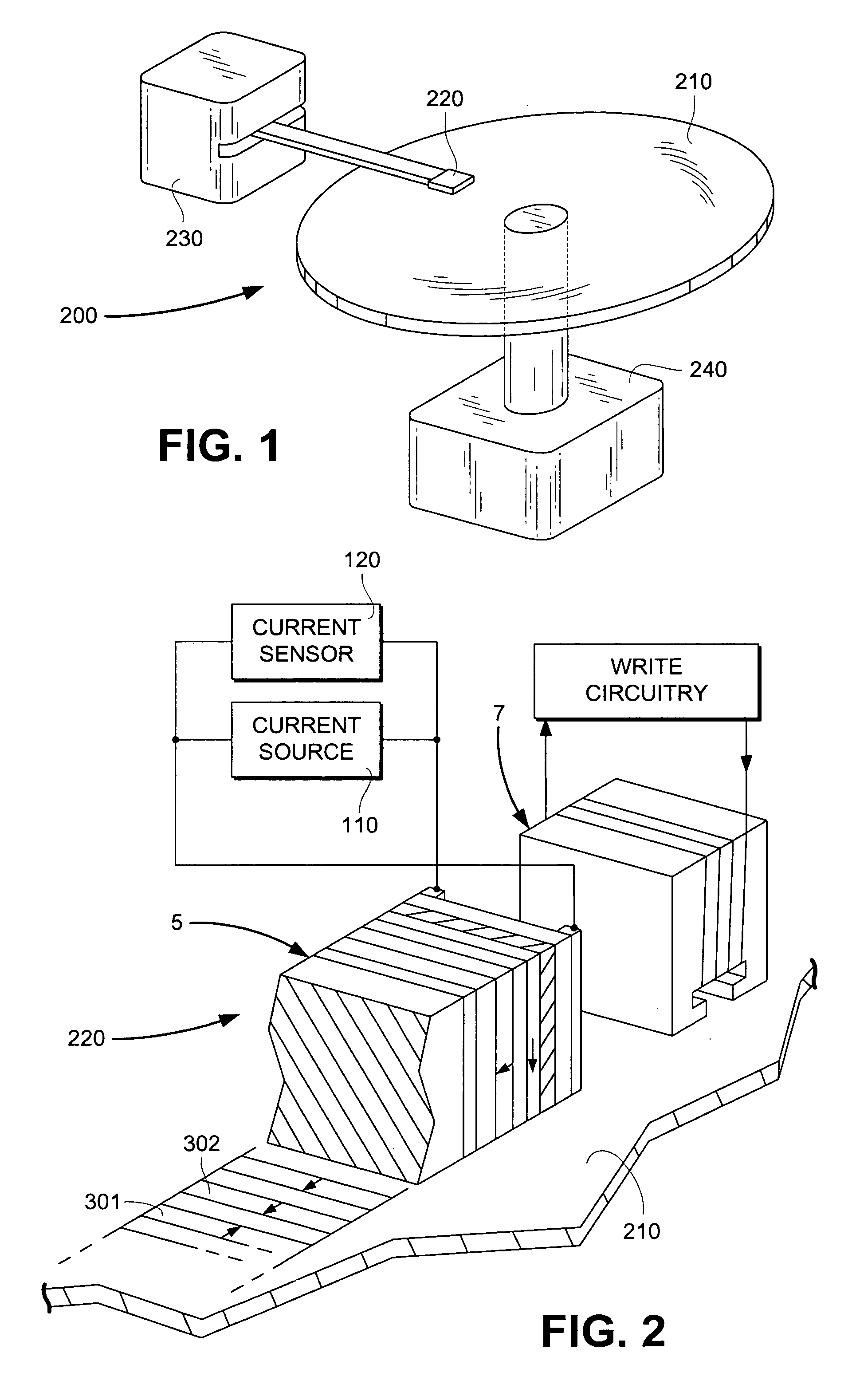
[0025]FIG. 1 is a conceptual drawing of a possible embodiment of a thin film read head of the present invention. FIG. 1 shows the thin film read head of the present invention embodied in a disk type magnetic data storage and retrieval apparatus 200. The read head of the present invention is located within a merged head assembly 220 which rides above a magnetic storage media 210, depicted in FIG. 1 as a rotatable hard disk type storage media. The hard disk 210 is coupled to a motor 240 to provide rotation of the disk relative to the head assembly 220. An actuating means 230 may be used to position the head assembly 220 above the surface of the media 210 to read and write data in the form of magnetic bits from and to the media 210. The data storage and retrieval apparatus 200, typically has several hard disks 210 and several corresponding head assemblies 220. The improved spin valve of the present invention is intended to be utilized in all known data storage and retrieval apparatuses...


PUM


Abstract

A spin valve device includes a non-magnetic enhancement layer adjacent an ultra thin free layer. The thickness of the free layer may be less than the mean free path of a conduction electron through the free layer. The GMR ratio is significantly improved for free layer thicknesses below 50 Å. The enhancement layer allows electrons to travel longer in their spin state before encountering scattering sites. The electronic properties of the enhancement layer material can be matched with the adjacent free layer without creating a low resistance shunt path. Because the free layer may be made ultra thin and the enhancement layer is formed of a nonmagnetic material, less magnetic field is required to align the free layer, allowing for improved data density. Also, the enhancement layer allows for effective bias point control by shifting sensor current density distribution.

Description

[0001]This application is a CON of Ser. No. 09 / 356,617 Jul. 19, 1999 ABNBACKGROUND OF THE INVENTION[0002]1. Technical Field[0003]The present invention relates to the field of spin-valve sensors.[0004]2. Background Art[0005]Data is stored on magnetic media by writing on the magnetic media using a write head. Magnetic media may be formed in any number of ways, such as tape, diskette, hard disk, or the like. Writing involves storing a data bit by utilizing magnetic flux to set the magnetic moment of a particular area on the magnetic media. The state of the magnetic moment is later read, using a read head, to retrieve the stored information.[0006]Data density is determined by the amount of data stored on an area of magnetic media and depends on how much area must be allocated to each bit. To decrease bit size, head size is decreased by fabricating thin film read and write heads. Thin film heads commonly employ separate write and read heads.[0007]One type read head employs a spin valve s...

Claims


Application Information

Patent Timeline
IPC IPC(8): G11B5/39
CPCB82Y10/00B82Y25/00G11B5/3932G01R33/093G11B2005/3996
Inventor ANDERSON, GEOFFHUAI, YIMING
Owner WESTERN DIGITAL TECH INC
Learn More