Die cushion apparatus of a press machine and surge pressure reduction method for a die cushion apparatus

Inactive Publication Date: 2007-04-03
KOMATSU LTD
View PDF10 Cites 12 Cited by
  • Summary
  • Abstract
  • Description
  • Claims
  • Application Information

AI Technical Summary

Benefits of technology

[0016]The present invention was made with the foregoing in view, and it is an object of the present invention to

Problems solved by technology

However, if the die cushion capacity is increased and the production rate further rises, an excessively large peak pressurizing force is generated at the instant of time the upper mold and lower mold are brought into contact.
A variety of problems such as vibrations, noise, cracking of press frame, equipment failure, and low-quality processing of works were associated with such surge pressure.
Because the oil has small compressibility, if the pressure control of the first hydraulic chamber 73 is not conducted with good timing, the piston 72 to which the pressurizing force of the die cushion pad 2 is applied cannot operate and the

Method used


Image

  • Die cushion apparatus of a press machine and surge pressure reduction method for a die cushion apparatus
  • Die cushion apparatus of a press machine and surge pressure reduction method for a die cushion apparatus
  • Die cushion apparatus of a press machine and surge pressure reduction method for a die cushion apparatus

Examples


Example

[0041]Embodiment of the die cushion apparatus in accordance with the present invention will be described hereinbelow with reference to the accompanying drawings.

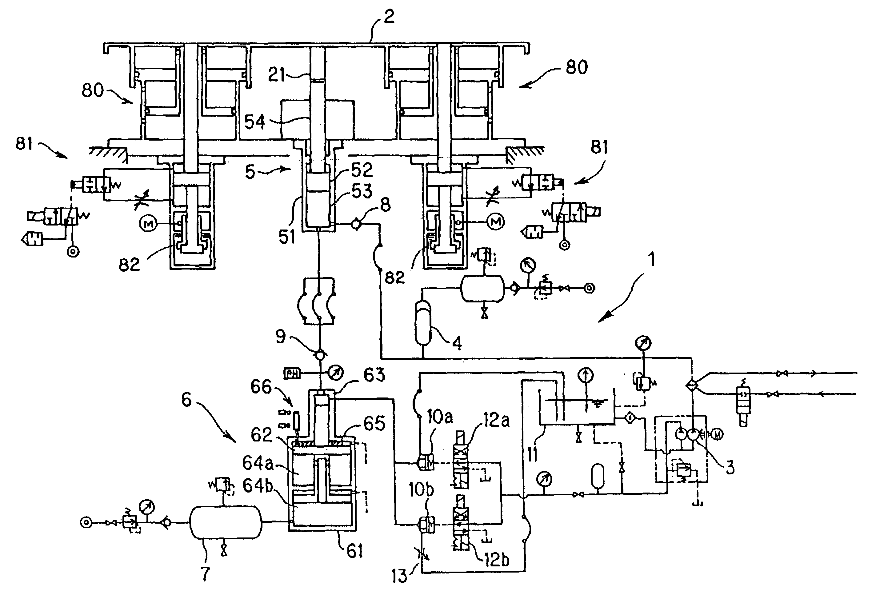
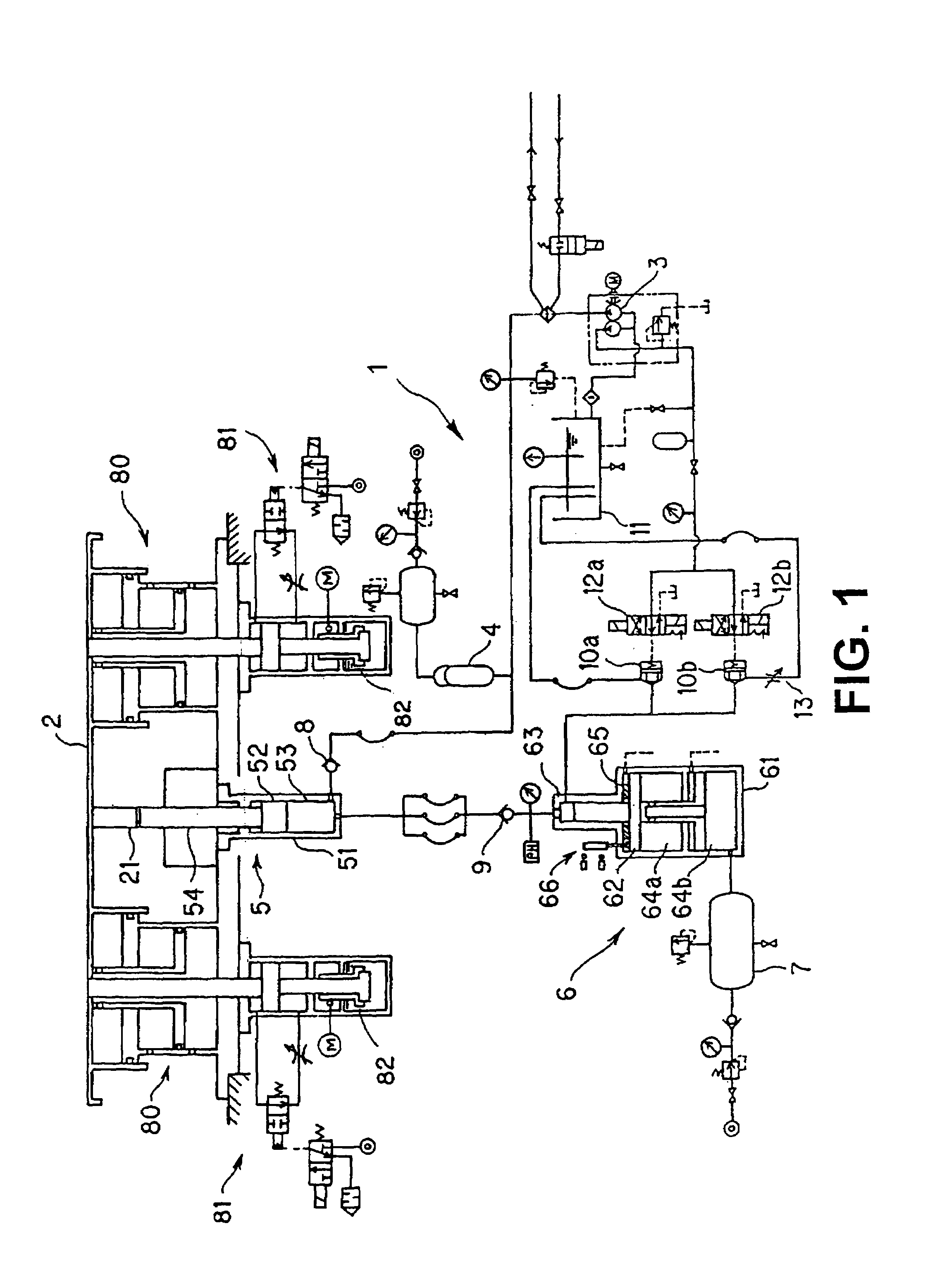
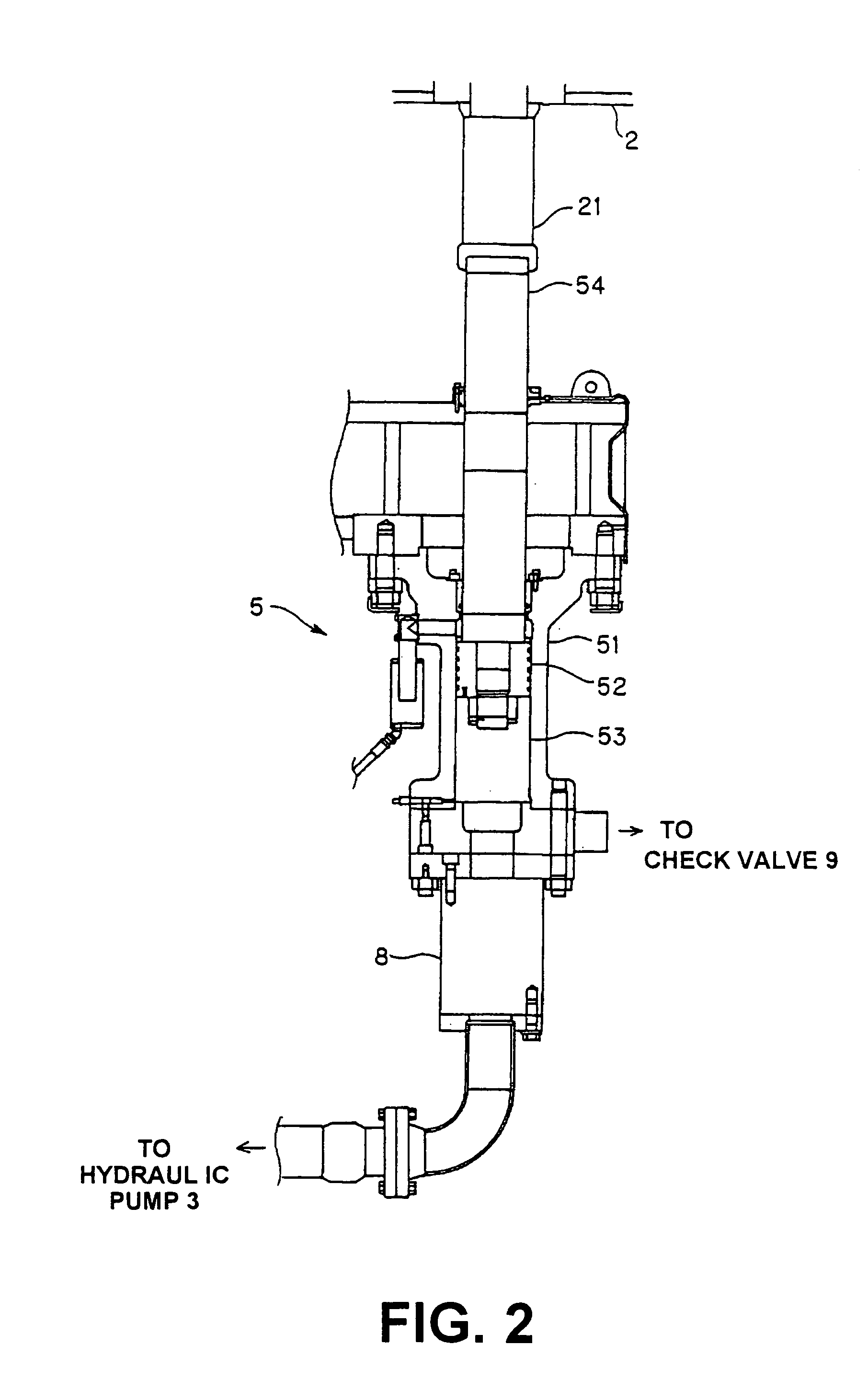
[0042]A die cushion pad 2 is supported on the lower surface side thereof by a hydraulic cylinder unit 5 together with a pneumatic cylinder unit 80. Because the pneumatic cylinder unit 80 is identical to that used in the conventional die cushion, the explanation thereof is herein omitted. A first rod 21 is connected to the lower surface of the die cushion pad 2, and the pressurizing force acting when the die cushion pad 2 is lowered is applied to a hydraulic cylinder unit 5 via the first rod 21.

[0043]A hydraulic pump 3 discharges the pressure oil under a constant pressure. An accumulator 4 serves to compensate the insufficient supply of the pressure oil discharged from the hydraulic pump 3 and to prevent pressure pulsations. A first check valve 8 is connected to the oil channel so as to allow the pressure oil to flow in the d...


PUM

PropertyMeasurementUnit
Forceaaaaaaaaaa
Flow rateaaaaaaaaaa

Abstract

In a die cushion apparatus, a pressurizing force acting on a die cushion pad is applied to a first piston of a hydraulic cylinder unit by the operation of a slide, the first piston slides inside a first cylinder and pressure oil in a first hydraulic chamber is pressurized. The first hydraulic chamber is linked to a second hydraulic chamber of a booster cylinder unit via a second check valve, so that the pressure oil of the first hydraulic chamber is pushed out into the second hydraulic chamber. When the pressure of the first hydraulic chamber is applied to a second piston, the second piston slides inside the second cylinder and gas of a gas pressure chamber is compressed, whereby a surge pressure is reduced.

Description

BACKGROUND OF THE INVENTION[0001]1. Field of the Invention[0002]The present invention relates to a die cushion apparatus of a press machine and to a surge pressure reduction method for a die cushion apparatus, more specifically to a die cushion apparatus of a press machine and to a surge pressure reduction method for a die cushion apparatus in which pressure oil is pressurized with the pressurizing force acting upon a die cushion pad and sealed gas is compressed by this pressure of the pressure oil.[0003]2. Description of the Related Art[0004]A die cushion apparatus has a function of pushing up the work that was fit into the lower mold, following the slide lift. However, the progress attained in the die technology resulted in that the blank holder function (a function of holding the peripheral portion of the work during deep drawing) is requested to be provided with the die cushion, and die cushions are now required to have a large capability, for example, of 300 tons or 400 tons.[0...

Claims


Application Information

Patent Timeline
IPC IPC(8): B21J9/18F16F15/02B21D24/02B30B15/02F16F9/06F16F9/46F16F9/50F16F15/023
CPCB21D24/02
Inventor KODANI, SHIGEKI
Owner KOMATSU LTD
Why Eureka
Try Eureka