
Magnetoelectric multilayer composites for field conversion

a multi-layer composite and field conversion technology, applied in the field of magnetic multi-layer composites, can solve the problems of reduced me coefficients, poor mechanical coupling, lack of interest in such transducers, etc., and achieve the effect of large me coefficients, large me effect, and maximum field conversion efficiency

Inactive Publication Date: 2007-04-10
OAKLAND UNIVESITY
View PDF14 Cites 7 Cited by
  • Summary
  • Abstract
  • Description
  • Claims
  • Application Information

AI Technical Summary

Benefits of technology

This approach results in significantly improved magnetoelectric voltage coefficients, achieving efficiencies up to 1500 mV / cm Oe, surpassing previous values and demonstrating enhanced field conversion capabilities.

Problems solved by technology

Until now, interest in such transducers has been lacking because of conversion efficiencies that are an order of magnitude below theoretical predictions.
Possible causes for such low αE include microcracks due to thermal expansion mismatch between the two phases, leakage current through low resistivity ferrites, porosity, and any impurity or undesired phases.
The low αE or the absence of ME effect is most likely due to unfavorable interface conditions and the following problems due to the use of platinum electrodes at the interface: (i) the electrode makes it a three-phase multilayer structure and leads to poor mechanical coupling between the two oxide layers, (ii) platinum with thermal expansion coefficient much higher than that of oxides will result in micro-cracks at the interface during sample processing, (iii) measurement conditions for ME effects might correspond to the inelastic region of stress-strain characteristics for Pt leading to a reduction in ME coefficients.
However, current materials available for making magnetostrictive and piezoelectric composites produce composites which have conversion efficiencies that are an order of magnitude below theoretical predictions.

Method used


Image

  • Magnetoelectric multilayer composites for field conversion
  • Magnetoelectric multilayer composites for field conversion
  • Magnetoelectric multilayer composites for field conversion

Examples


example 1

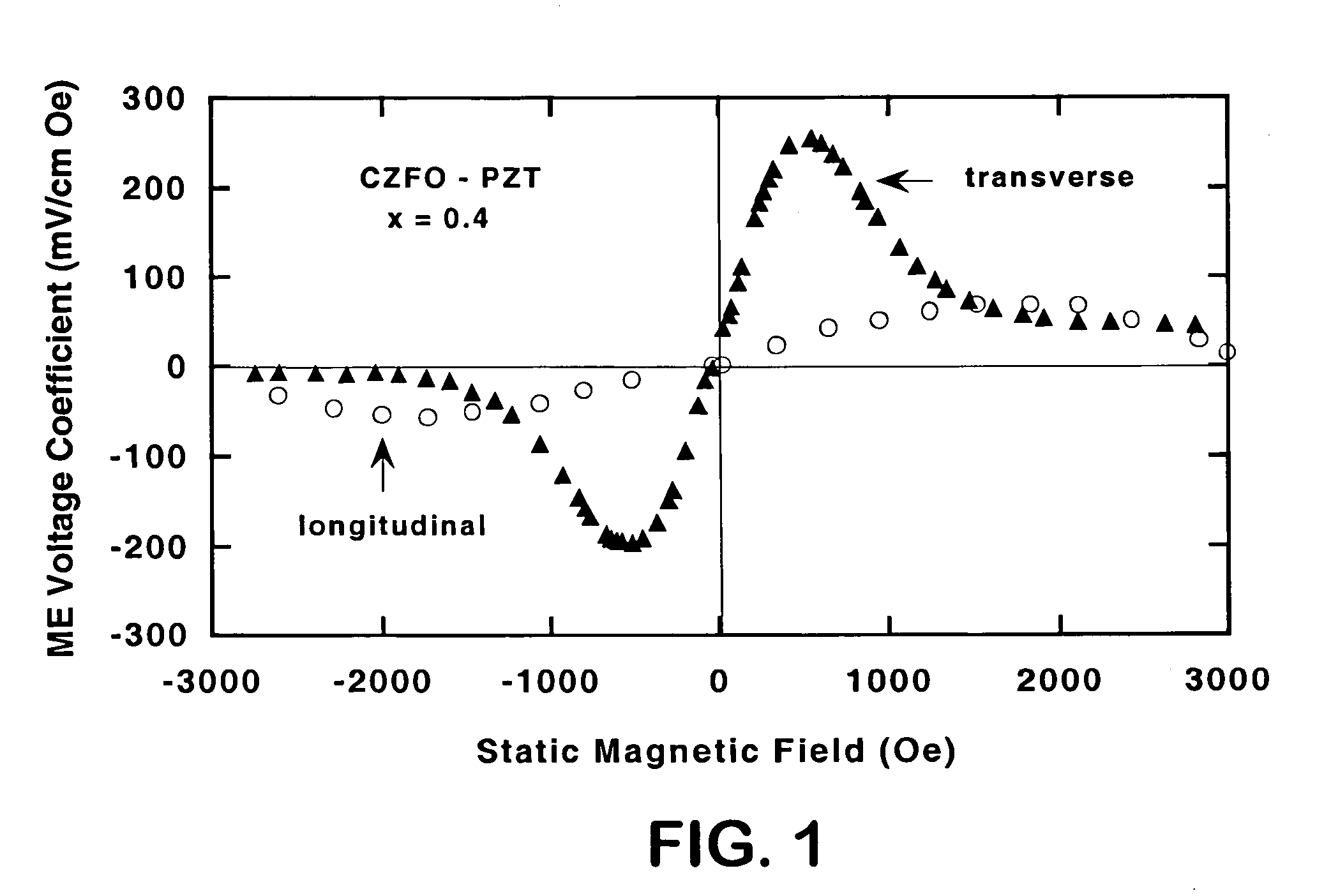
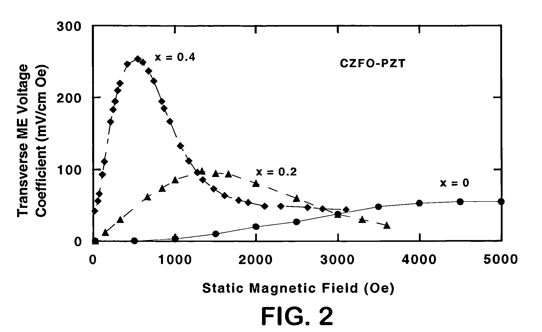
[0093]This example provides an understanding of the effects of the magnetic parameters of ferrites on ME coupling in multilayers with PZT. It is possible to accomplish controlled variations in such parameter with Zinc substitution in ferrites. The following oxides were used for the magnetic phase: cobalt zinc ferrite, Co1−xZnxFe2O4 (CZFO) (x=0–0.6), nickel zinc ferrite Ni1−xZnxFe2O4 (NZFO) (x=0–0.5), and lithium zinc ferrite Li0.5−x / 2ZnxFe2.5−x / 2O4 (LZFO) (x=0–0.4). Commercially available PZT was used for the piezoelectric phase.

I. MATERIALS AND METHODS

[0094]Layered composites were synthesized using thick films of ferrites and PZT obtained by tape casting (Mistler and Twiname, Tape Casting: Theory and Practice, The American Ceramics Society, Westerville, Ohio (2000)). The ferrite powder necessary for tape casting was prepared by the standard ceramic techniques that involved mixing the oxides or carbonates of the constituent metals, followed by pre-sintering, and final sintering. A b...

example 2

[0122]This example illustrates the formation of nickel zinc ferrite-lead zirconate titanate (NZFO-PZT) bilayers and multilayers. Both NZFO-PZT bilayers and multilayers were synthesized from thick films prepared by tape casting. The process involved (i) preparation of submicron-sized powder of nickel zinc ferrite (NZFO) and lead zirconate titanate (PZT), (ii) thick-film tapes by doctor-blade techniques, and (iii) lamination and sintering of bilayers and multilayers.

[0123]NZFO powder was obtained by standard ceramic techniques and commercial PZT (Sample No. APC850) was obtained from American Piezo Ceramics, Inc., Mackeyville, Pa.) were used. For tape casting (Mistler et al., In Tape Casting: Theory and Practice (American Ceramics Society, Westerville, Ohio, 2000), powders of NZFO and PZT were each mixed with a solvent such as ethyl alcohol and a dispersant such as Blown Menhaden fish oil (available from Richard E. Mistler, Inc., Morrisville, Pa.) and ball milled for 24 hours, followed...

example 3

[0125]This example illustrates the formation of cobalt zinc ferrite-lead zirconate titanate (CZFO-PZT) bilayers and multilayers. Both CZFO-PZT bilayers and multilayers were synthesized from thick films prepared by tape casting. The process involved (i) preparation of submicron-sized powder of cobalt zinc ferrite (CZFO) and lead zirconate titanate (PZT), (ii) thick-film tapes by doctor-blade techniques, and (iii) lamination and sintering of bilayers and multilayers.

[0126]CZFO powder was obtained by standard ceramic techniques and commercial PZT (Sample No. APC850) was obtained from American Piezo Ceramics, Inc., Mackeyville, Pa.) were used. For tape casting, powders of CZFO and PZT were each mixed with a solvent such as ethyl alcohol and a dispersant such as Blown Menhaden fish oil and ball milled for 24 hours, followed by a second ball mill with a plasticizer such as butyl benzyl phthalate and a binder such as polyvinyl butyral for 24 hours to produce a slurry of CZFO and a slurry o...


PUM

PropertyMeasurementUnit
thicknessaaaaaaaaaa
thicknessaaaaaaaaaa
thicknessaaaaaaaaaa

Abstract

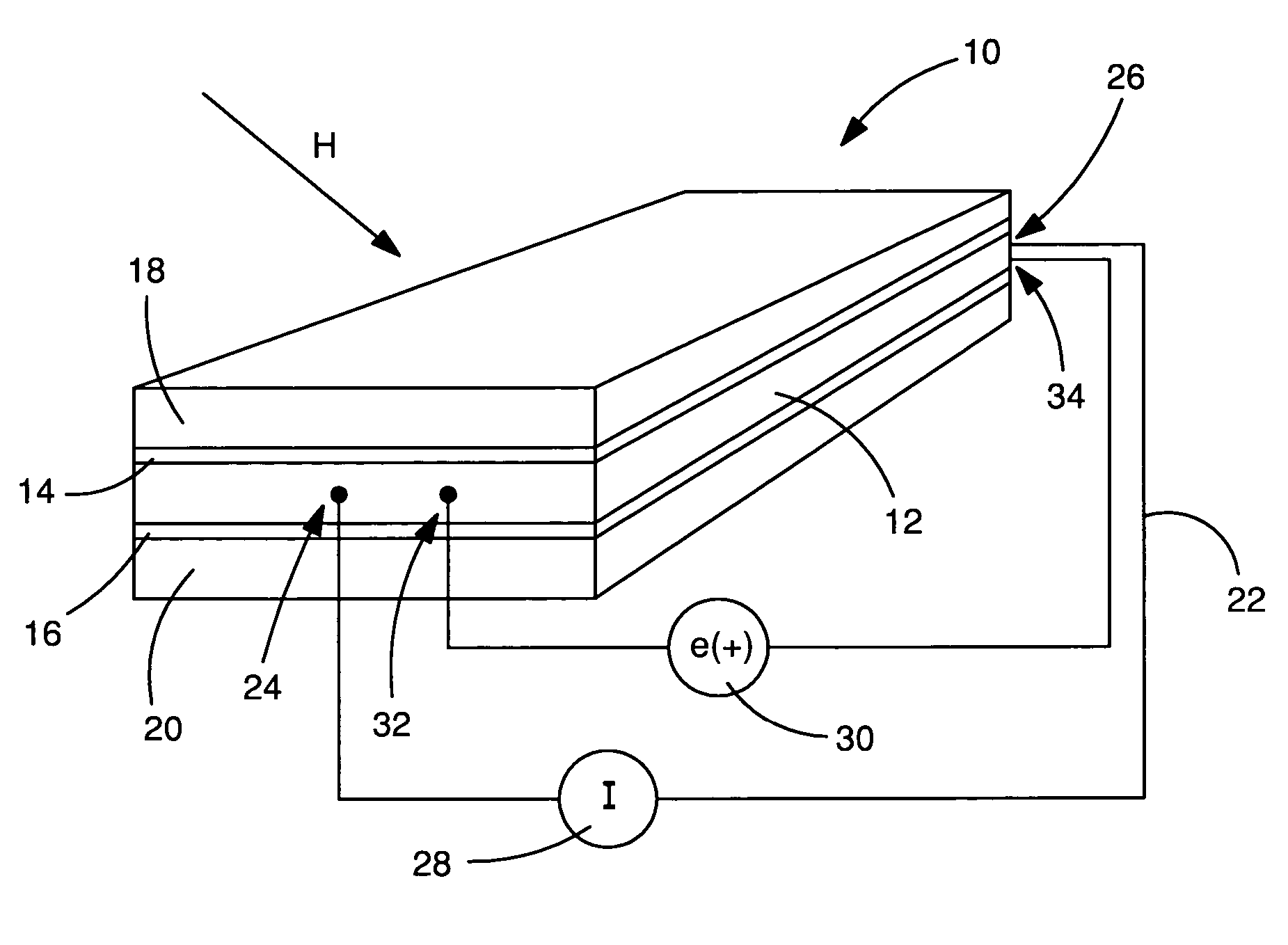
Magnetoelectric multilayer composites comprising alternate layers of a bimetal ferrite wherein one of the metals is zinc and a piezoelectric material for facilitating conversion of an electric field into a magnetic field or vice versa. The preferred composites include cobalt, nickel, or lithium zinc ferrite and PZT films which are arranged in a bilayer or in alternating layers, laminated, and sintered at high temperature. The composites are useful in sensors for detection of magnetic fields (10); sensors for measuring rotation speed, linear speed, or acceleration; read-heads in storage devices by converting bits in magnetic storage devices to electrical signals; magnetoelectric media for storing information; and high frequency devices for electric field control of magnetic devices or magnetic field control of electric devices.

Description

CROSS-REFERENCE TO RELATED APPLICATION[0001]This application is a Divisional of U.S. application Ser. No. 10 / 125,670, filed Apr. 18, 2002, now U.S. Pat. No. 6,835,463.STATEMENT REGARDING FEDERALLY SPONSORED RESEARCH OR DEVELOPMENT[0002]This invention was supported by National Science Foundation Grant No. DMR-0072144. The U.S. government has certain rights in this invention.REFERENCE TO A “COMPUTER LISTING APPENDIX SUBMITTED ON A COMPACT DISC”[0003]Not Applicable.BACKGROUND OF THE INVENTION[0004](1) Field of the Invention[0005]The present invention relates to magnetoelectric multilayer composites comprising alternate layers of a magnetostrictive material, which is a bimetal ferrite wherein one of the metals is zinc, and a piezoelectric material such as lead zirconate titanate (PZT), lead zincate niobate (PZN), lead zincate niobate lead-titanate (PZN-PT), lead magnesium niobate lead-titanate (PMN-PT), lead lanthanum zirconate titanate (PLZT), Nb / Ta doped-PLZT, and barium zirconate tit...

Claims


Application Information

Patent Timeline
Patent Type & Authority Patents(United States)
IPC IPC(8): C03B29/00H02N2/00B22F7/02B32B9/00H01F1/34H01F41/02H10N30/00
CPCH01F1/344H01L41/16H01F41/0246Y10T428/12861Y10T428/12465Y10T428/12944Y10T428/1114Y10T428/1143Y10T428/12028Y10T428/325H10N35/85H10N30/8554
Inventor SRINIVASAN, GOPALAN
Owner OAKLAND UNIVESITY
Learn More