Hermetically sealed electrolytic capacitor

a capacitor and hermetically sealed technology, applied in the field of electrolytic capacitors, can solve the problems of inconvenient use, leakage around conventional non-hermetically sealed, aluminum to glass seals, etc., and achieve the effect of increasing the surface area and enhancing the performance of the capacitor

Active Publication Date: 2007-04-17
CORNELL DUBILIER MARKETING
View PDF29 Cites 55 Cited by
  • Summary
  • Abstract
  • Description
  • Claims
  • Application Information

AI Technical Summary

Benefits of technology

[0009]The capacitor of the present invention is hermetically sealed, which is defined as having a permeability to helium gas of 10−7 cc/second or less, at 25° C. and one atmosphere of differential pressure.
[0010]The capacitor is housed in a case, which is a receptacle having an opening at one end. The case is made from a material that is substantially impermeable to gases. By way of example, the case may be made out of metal, in particular, steels (stainless or other alloys) or tantalum. If the case material is susceptible to corrosion by an electrolyte solution, the material may be coated, plated or provided with other protective treatment, as is known to those skilled in the art.
[0011]An advantage of the present invention is that its performance is not dependent upon the case having any particular shape. By way of example, the case may be in the shape of a cylinder, rectangular prism or parallelepiped.
[0012]A capacitor element is positioned inside the case. The capacitor element is made up of an anode, a cathode, a dielectric and an electrolyte solution, forming a capacito

Problems solved by technology

Capacitors containing an electrolyte solution are subject to failure caused by leakage of the electrolyte liquid or vapor.
Consequently, leaks may occur around conventional non-hermetic polymeric seals, where terminal wires protrude from the capacitor casing.
In the situation of an aluminum case, it has not proven economical, however, to provide a hermetic, aluminum to glass seal, due in part to the significant difference in the thermal coefficient of expansion of the glass or ceramic material used to construct the seal and the thermal coefficient of expansion of aluminum.
Either of these two situations could result in undesirable electrical current flow between the high electrical potential of the inne

Method used


Image

  • Hermetically sealed electrolytic capacitor
  • Hermetically sealed electrolytic capacitor
  • Hermetically sealed electrolytic capacitor

Examples


Embodiment Construction

[0037]Without limiting the scope of the invention, the preferred embodiments and features are hereinafter set forth. All of the United States patents, which are cited in the specification, are hereby incorporated by reference. Unless otherwise indicated, conditions are 25° C., 1 atmosphere of pressure and 50% relative humidity.

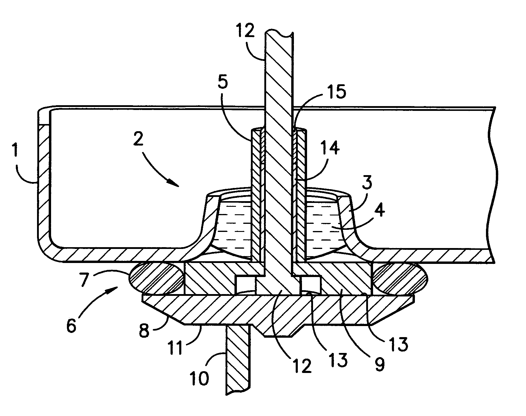
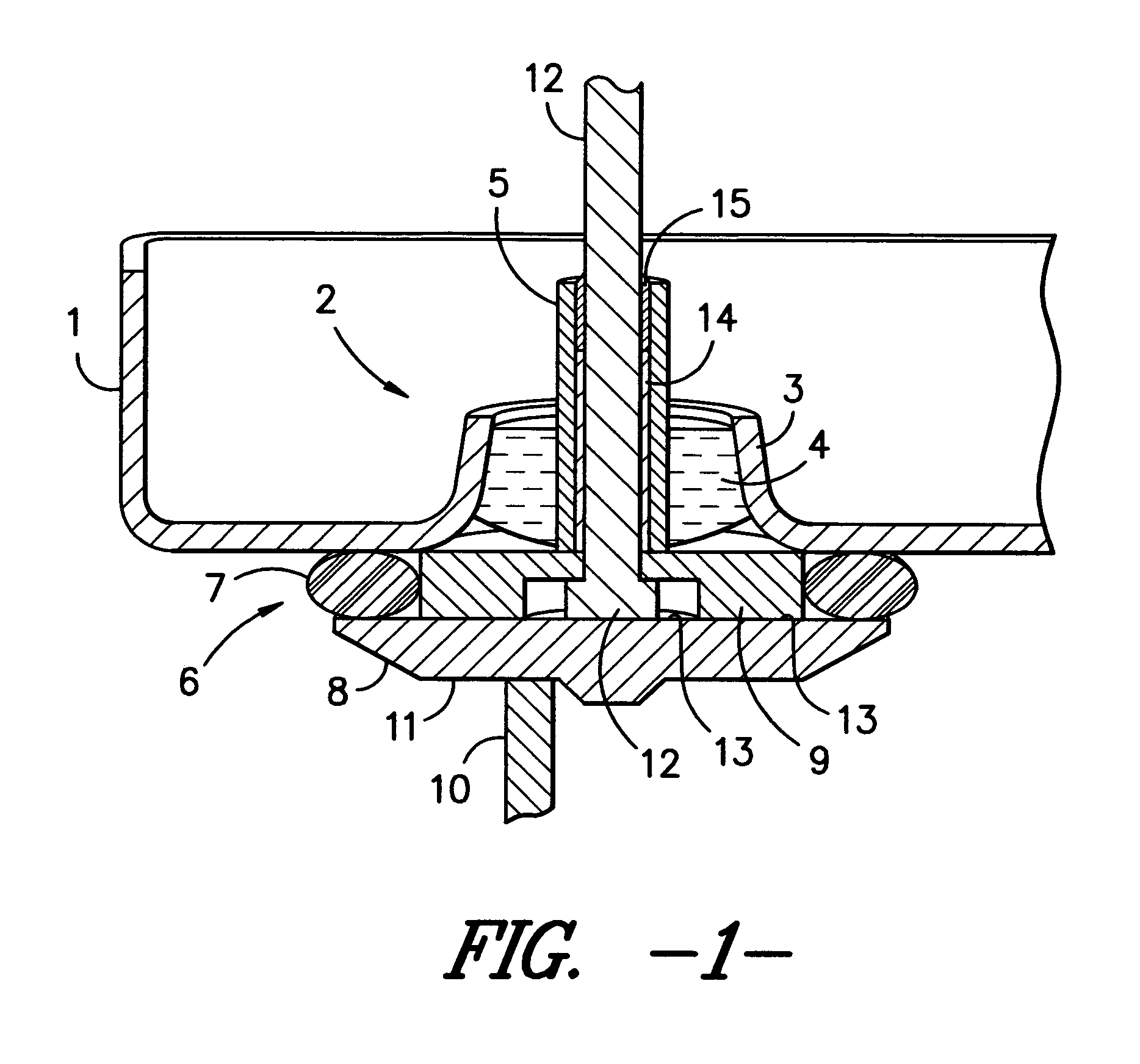
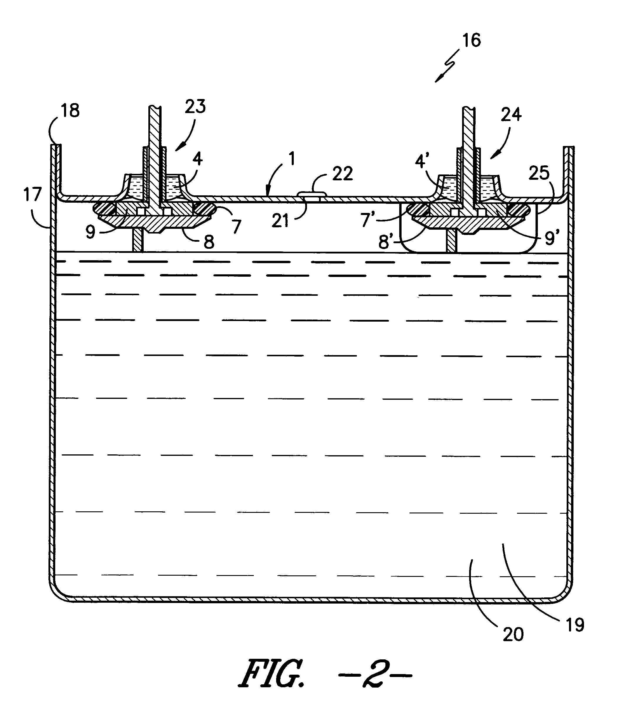
[0038]Referring to FIG. 1, lid 1 contains an integrally formed metal-glass-metal hermetic seal 2. Hermetic seal is formed by the upturned portion of lid 3, annular glass 4 and a metal post, which in the embodiment shown is hollow tube 5. Liquid seal 6 is formed by elastomeric ring 7 compressed between terminal plate 8 and the underside of lid 1. Bushing 9 is positioned inside elastomeric ring 7, and acts to center elastomeric ring 7 relative to hermetic seal 2, as well fixing the distance between terminal plate 8 and lid 1.

[0039]Terminal plate 8 is electrically connected to the anode or cathode of the capacitor element by lead 10 on the wet side 11 of terminal...


PUM


Abstract

An electrolytic capacitor is provided having a metal-glass-metal hermetic seal and a liquid seal, which protects the hermetic seal from the electrolyte solution in the capacitor. The liquid seal is formed by compressing an elastomeric ring between the underside of the lid of the capacitor and a terminal plate, connected to the capacitor element, whereby compression of the elastomeric seal is maintained by the lead, which connects the terminal plate and a metal post in the hermetic seal.

Description

BACKGROUND OF THE INVENTION[0001]This invention relates generally to the field of electrolytic capacitors that are hermetically sealed, and in particular to a capacitor having a liquid-tight seal between the electrolyte solution and the terminal used to make an electrical connection between the capacitor and an external device.[0002]Capacitors containing an electrolyte solution are subject to failure caused by leakage of the electrolyte liquid or vapor. For example, it is common for gas, such as hydrogen, to be evolved during operation, causing pressure to build inside the capacitor. Consequently, leaks may occur around conventional non-hermetic polymeric seals, where terminal wires protrude from the capacitor casing. To avoid this, a gas-tight hermetic seal is required.[0003]One prior art solution has been to provide a hermetic, outer-metal / glass / inner-metal seal between the capacitor casing and the terminal wire. For the sake of clarity, the casing, typically the lid, is referred ...

Claims


Application Information

Patent Timeline
IPC IPC(8): H01G4/00
CPCH01G9/10H01G9/145
Inventor KNIGHT, PHILIP A.PARLER, JR., SAMUEL G.NORRIS, JERRY W.
Owner CORNELL DUBILIER MARKETING
Why Eureka
Try Eureka