Plasma display unit, phosphor and process for producing phosphor

a technology of phosphor and display unit, which is applied in the direction of discharge tube luminescnet screens, gas-filled discharge tubes, address electrodes, etc., can solve the problems of increased phosphor defects, color shift or burn on screens, and increase phosphor defects, so as to suppress the degradation of luminance of panels or the suppression of chromaticity changes, the effect of reducing oxygen vacancies

Inactive Publication Date: 2007-04-24
PANASONIC CORP
View PDF4 Cites 49 Cited by
  • Summary
  • Abstract
  • Description
  • Claims
  • Application Information

AI Technical Summary

Benefits of technology

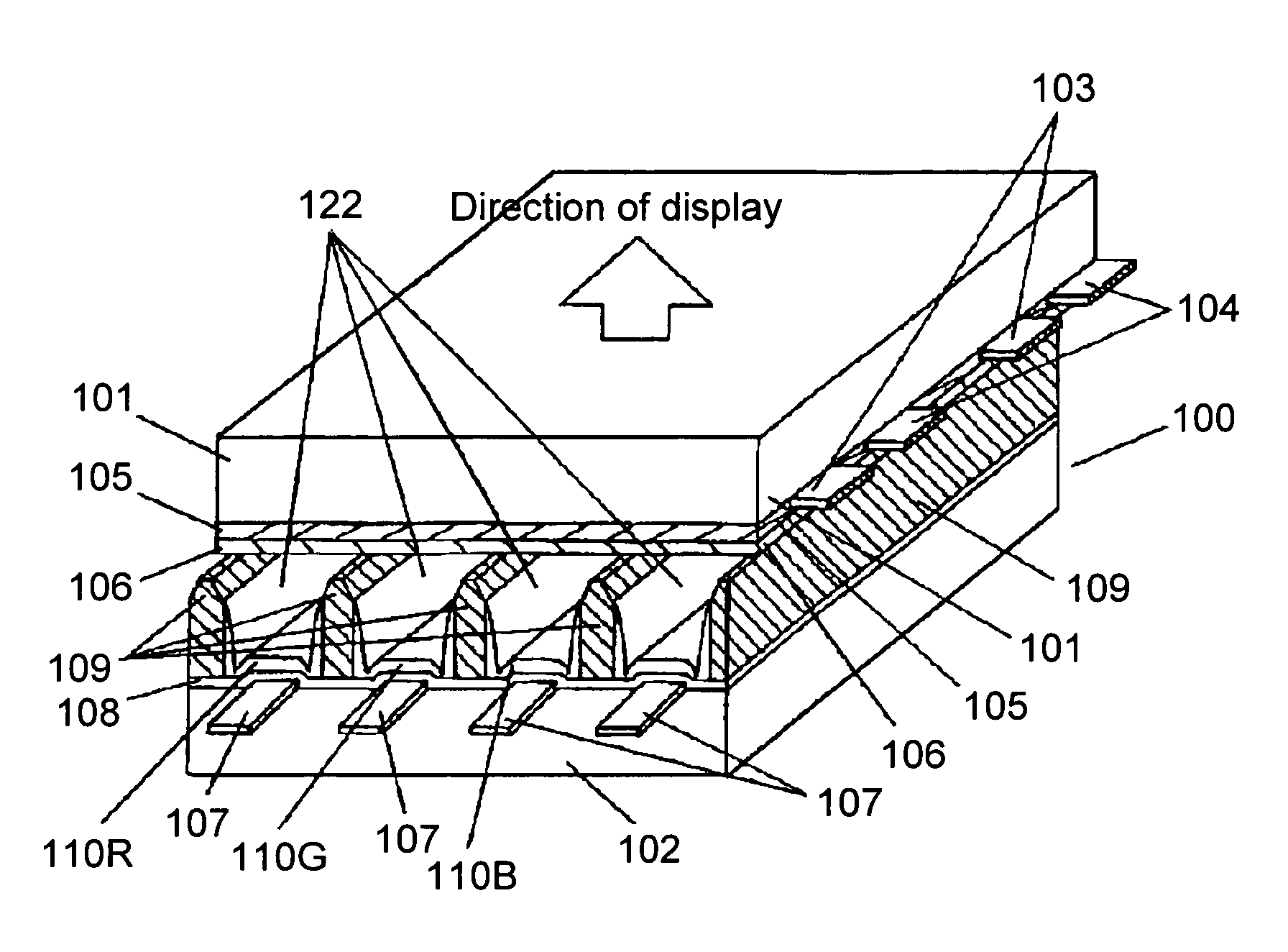
[0012]In such a structure, this pentavalent element is substituted for the part of the aluminum (Al) element or magnesium (Mg) element in the blue phosphor, thus reducing oxygen vacancies in the vicinity of Ba—O layers and suppressing adsorption of water or hydrocarbon-containing gas on a surface of the blue phosphor. Consequently, degradation of luminance of a panel or a change in chromaticity is suppressed, or discharge characteristics are improved without a decrease in luminance of the phosphor.

Problems solved by technology

However, reducing the particle diameters of the phosphor particles increases a surface area of the phosphor and thus increases a number of defects in the phosphor.
Such water and gas are released into the panel in large amounts in a panel manufacturing process and react with the phosphor and MgO during discharge, thus problematically degrading luminance, causing a change in chromaticity (which leads to a color shift or a burn on a screen), and reducing a drive margin and raising discharge voltage.
It is also known that the defects increase further in number as vacuum ultraviolet rays (VUV), having a wavelength of 147 nm, and which are generated by discharge in driving the panel, are absorbed, thus problematically degrading luminance of the phosphor further (refer to, for example, “Technical Report” published by the Institute of Electronics, Information and Communication Engineers, EID99–94, Jan. 27, 2000).
However, covering the entire surface of the phosphor with the crystal coating of Al2O3 causes ultraviolet rays to be absorbed, thus problematically reducing emission luminance of the phosphor.

Method used


Image

  • Plasma display unit, phosphor and process for producing phosphor
  • Plasma display unit, phosphor and process for producing phosphor
  • Plasma display unit, phosphor and process for producing phosphor

Examples


embodied examples

[0055]A description is provided hereinafter of synthesis methods for respective phosphors used in the present embodiment.

[0056]First, a description is provided of the blue phosphor, Ba1−XMgAl10O17:EuX, synthesized by hydrothermal synthesis.

[0057]In a process of preparing a mixed solution, materials including barium nitrate (Ba(NO3)2), magnesium nitrate (Mg(NO3)2), aluminum nitrate (Al(NO3)3) and europium (Eu(NO3)2) are mixed in a molar ratio of 1−X:1:10:X (where 0.03≦X≦0.2) and dissolved in an aqueous medium, whereby a hydrated mixed solution is made. As the aqueous medium, ion-exchange water or pure water is preferable because either of these waters contains no impurities. However, the aqueous medium can be used even when a non-aqueous solution, such as methanol or ethanol, is also included.

[0058]As a material for substituting Pr, Tm or a pentavalent ion (Nb, Ta, P, As, Sb, or Bi) for Mg or Al, a nitrate, a chloride or an organic compound that includes the above-mentioned Pr, Tm or...

experiment 1

[0084]Luminance of the blue color of each of samples 1–10 and comparative sample 11 made was measured before as well as after the phosphor was fired (at 520° C. for 20 minutes) in a process of manufacturing a rear panel, and a luminance degradation rate of the blue color was determined. Specifically, luminance of phosphor particles was measured before firing, and luminance of ink applied and fired was measured.

experiment 2

[0085]A change of luminance of each blue phosphor, between before and after panels were put together and sealed (at 450° C. for 20 minutes), was determined in manufacture of the PDP.


PUM

PropertyMeasurementUnit
temperatureaaaaaaaaaa

Abstract

A plasma display device exhibits suppressed luminance degradation of a phosphor, a suppressed change in chromaticity and improved discharge characteristics as a result of suppression of adsorption of water or hydrocarbon-containing gas on a surface of a blue phosphor. A blue phosphor layer used in the plasma display device is formed of a compound expressed by Ba1−XMgAl10O17:EuX or Ba1−x−ySryMgAl10O17:EuX and includes at least one element that is selected from Nb, Ta, Pr, P, As, Sb, Bi and Tm which substitutes for a part of its Al or Mg element.

Description

TECHNICAL FIELD[0001]The present invention relates to a plasma display device used as, for example, a television for image display and also relates to a phosphor and a method of manufacturing the phosphor.BACKGROUND ART[0002]Of color display devices used as, for example, computers and televisions for image display, a display device using a plasma display panel (hereinafter referred to as “PDP”) has received attention in recent years as a large-size, thin and lightweight color display device.[0003]A plasma display device using this PDP produces a display in full color by additive mixture of so-called three primary colors (red, green and blue). For display in full color, the plasma display device is provided with phosphor layers which emit respective lights having these respective three primary colors, that is, red (R), green (G) and blue (B). Phosphor particles of each phosphor layer are excited by ultraviolet rays generated in a discharge cell of the PDP, thereby producing visible c...

Claims


Application Information

Patent Timeline
Patent Type & Authority Patents(United States)
IPC IPC(8): H01J11/02C09K11/64C09K11/67C09K11/08C09K11/59C09K11/71C09K11/74C09K11/75C09K11/77C09K11/80H01J11/12H01J11/22H01J11/24H01J11/26H01J11/34H01J11/42
CPCC09K11/595C09K11/7734C09K11/7792C09K11/7797H01J2211/42H01J11/42
Inventor AOKI, MASAKIKAWAMURA, HIROYUKISUGIMOTO, KAZUHIKOOTANI, MITSUHIROHIBINO, JUNICHI
Owner PANASONIC CORP
Why Eureka
Try Eureka