Electron beam apparatus with detailed observation function and sample inspecting and observing method using electron beam apparatus
a technology of electron beam and detailed observation, which is applied in the direction of material analysis using wave/particle radiation, instruments, and therapy, etc., can solve the problems of increasing inspection time and the need to extend the floor area of a clean room, so as to reduce the distortion of secondary electron, improve the efficiency of secondary electron collection, and reduce the effect of potential differen
- Summary
- Abstract
- Description
- Claims
- Application Information
AI Technical Summary
Benefits of technology
Problems solved by technology
Method used
Image
Examples
example 1
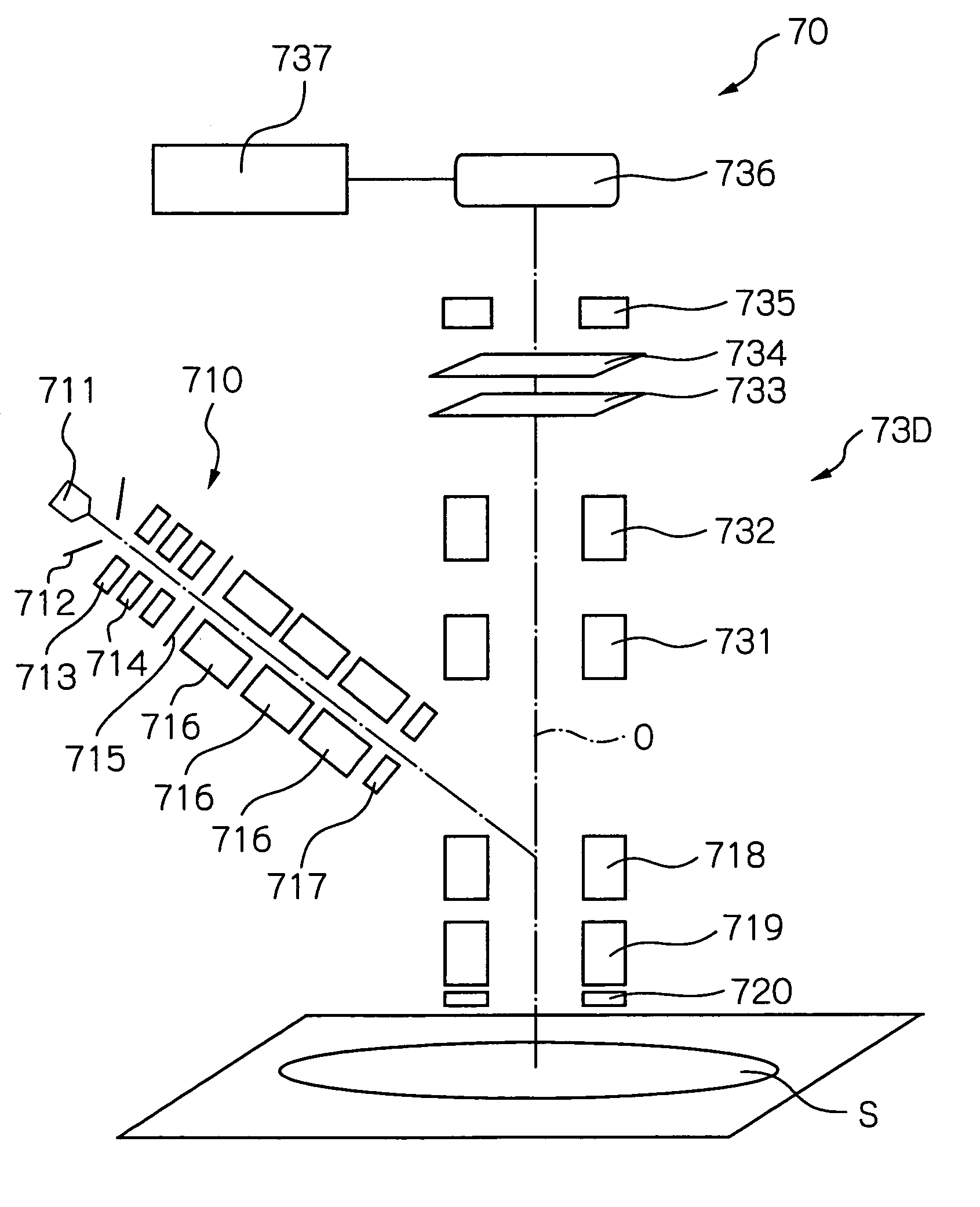
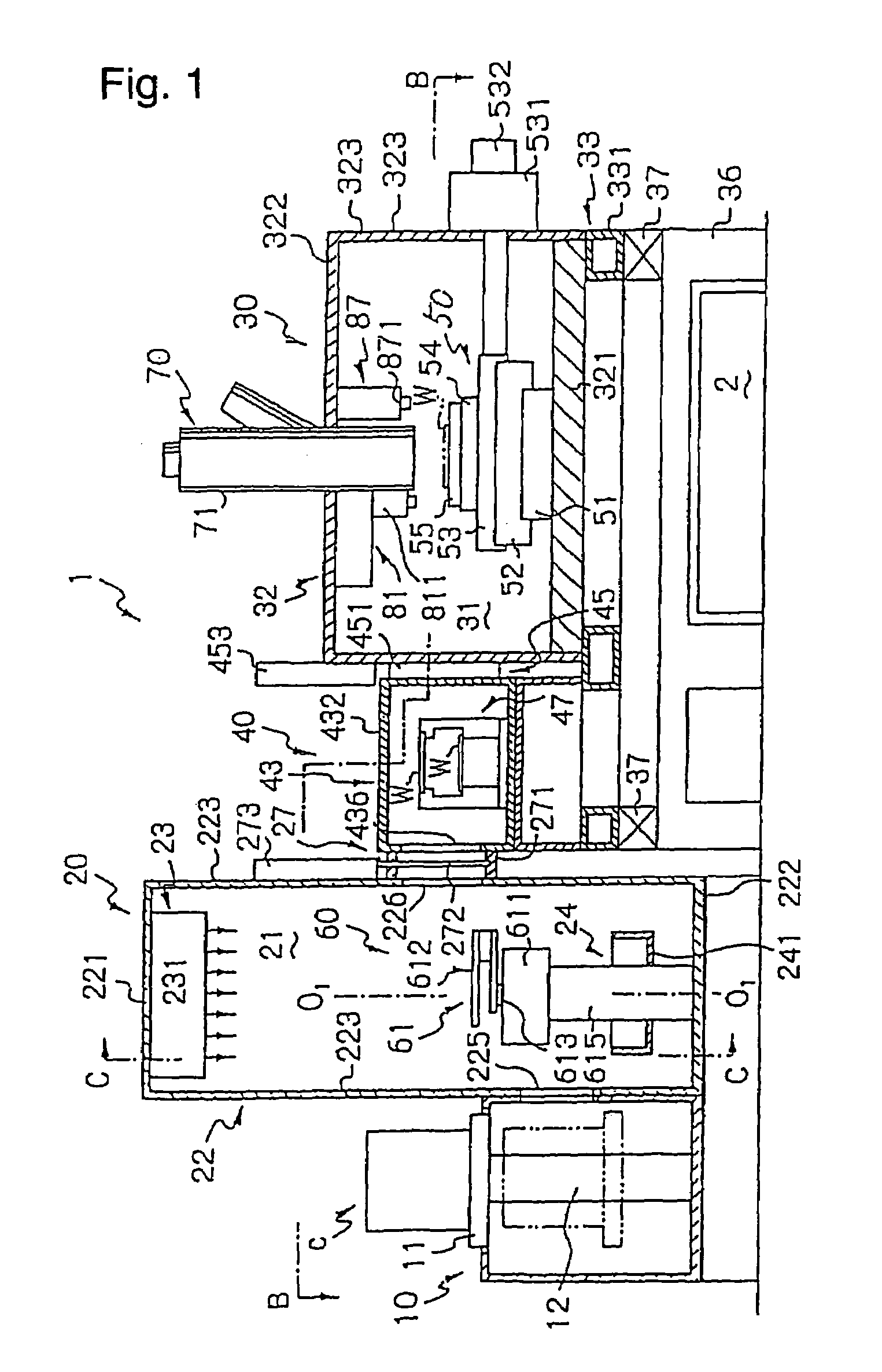
[0110]FIG. 7 schematically shows an electron beam apparatus 70 of image projection type with a single beam in example 1 of the electron beam apparatus 70 of FIG. 1. This electron beam apparatus 70 comprises a primary optical system 710 for shaping an electron ray emitted from an electron gun into a specified shape in section view and irradiating thus shaped electron beam onto a surface of a sample to be inspected, for example, a surface of a wafer S and a secondary optical system 730 for focusing secondary electrons emanating from the wafer S into an image on a detector.
[0111]The primary optical system 710 comprises a cathode 712 for drawing an electron ray from an electron source 711, an anode 713 for accelerating the electron ray (the electron source 711, the cathode 712 and the anode 713 together constructing an electron gun), an electrostatic lens 714, an aperture 715 for shaping the electron ray into an electron beam of specified shape in section view, a quadrupole lens 716 for...
example 2
[0121]FIG. 8 schematically shows an electron beam apparatus 70A of image projection type with a single beam in example 2 of the electron beam apparatus 70 of FIG. 1. This electron beam apparatus 70A has the same configuration as the electron beam apparatus in example 1 (FIG. 7), with the exceptions that a primary optical system 710A is arranged in parallel correspondence to the wafer and provided with a sector deflector 721 and that a secondary optical system 730A includes no E×B separator. In the present example, to irradiate the electron beam to a sample surface from the oblique direction relative thereto, firstly the electron beam is guided in a direction parallel to the wafer, and after passing through the aligner 717, the electron beam is controlled by the sector deflector 721 to irradiate from the oblique direction.
[0122]The manner of executing the image inspection of the wafer, the extraction of the defective region and the detailed image observation in the acquired defective...
example 3
[0123]FIG. 9 schematically shows an electron beam apparatus 70B of image projection type with a multi-beam in example 3 of the electron beam apparatus 70 of FIG. 1. This electron beam apparatus 70B has the same configuration as the electron beam apparatus 70A in example 2, with the exception that the electron beam apparatus 70B comprises a plurality of primary optical systems 710A. Since this electron beam apparatus 70B allows for a plurality of electron beams to be irradiated on the wafer, for the observation in the low reflected electron mode defining a lower emission ratio of the electrons from the wafer, some of the total number of electron beams (e.g., three of four electron beams) may be concurrently irradiated to the same inspection region to thereby improve the S / N ratio. Further, for the case of the detailed observation to be subsequently executed, the optical condition for the rest of the electron beams (i.e., the remaining one beam of the four electron beams) may be limit...
PUM
| Property | Measurement | Unit |
|---|---|---|
| width | aaaaa | aaaaa |
| diameter | aaaaa | aaaaa |
| diameter | aaaaa | aaaaa |
Abstract
Description
Claims
Application Information
 - R&D
- Intellectual Property
- Life Sciences
- Materials
- Tech Scout
- Unparalleled Data Quality
- Higher Quality Content
- 60% Fewer Hallucinations
Browse by: Latest US Patents, China's latest patents, Technical Efficacy Thesaurus, Application Domain, Technology Topic, Popular Technical Reports.
© 2025 PatSnap. All rights reserved.Legal|Privacy policy|Modern Slavery Act Transparency Statement|Sitemap|About US| Contact US: help@patsnap.com


