Synchronous rectifier control circuit

a control circuit and synchronous technology, applied in the direction of dc-dc conversion, power conversion systems, climate sustainability, etc., can solve the problems of low conversion efficiency (approximately 30% to 50%), inability to have a direct current input, large energy loss for a large current output, etc., to improve energy conversion efficiency, and low impedance

Inactive Publication Date: 2007-05-01
NIKO SEMICON
View PDF3 Cites 14 Cited by
  • Summary
  • Abstract
  • Description
  • Claims
  • Application Information

AI Technical Summary

Benefits of technology

[0004]Therefore, it is a primary objective of the present invention to provide a synchronous rectifier control circuit to overcome the shortcoming of having a low energy conversion efficiency for the aforementioned prior art rectifier circuit, and to improve the energy conversion efficiency. The invention uses the signal produced by the secondary winding of a transformer to control the low impedance and low power consuming current switch such as a junction field effect transistor (JFET) or a metal oxide semiconductor field effect transistor (MOSFET) to substitute the prior art high power consuming diode rectification, and appropriately rectify and extend the ON time of the current switch, and also prevent the positi...

Problems solved by technology

Since the linear rectifier adopts a low-frequency silicon steel transformer, therefore the linear rectifier has the shortcomings of large volume, heavy weight, low ...

Method used


Image

  • Synchronous rectifier control circuit
  • Synchronous rectifier control circuit
  • Synchronous rectifier control circuit

Examples


Embodiment Construction

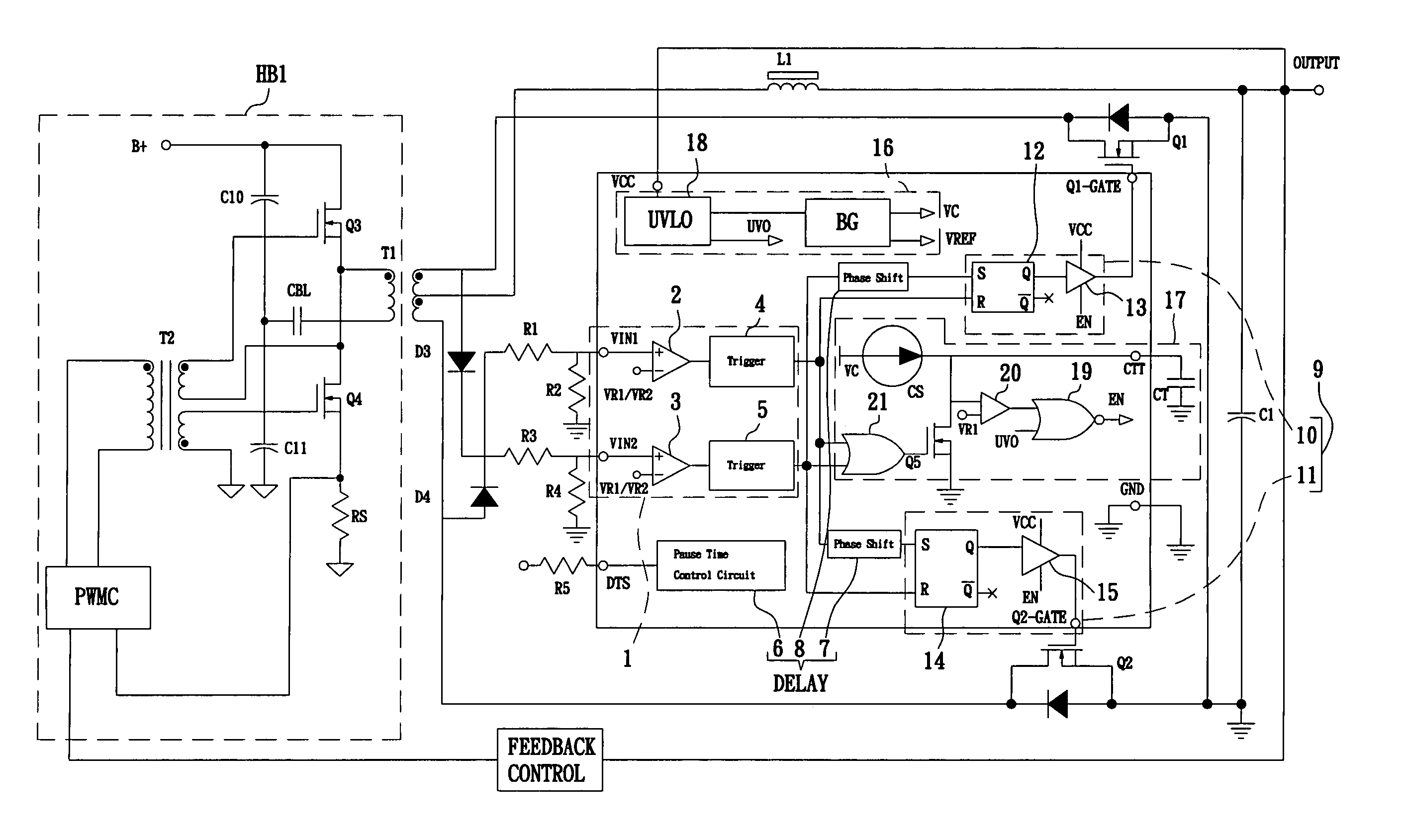
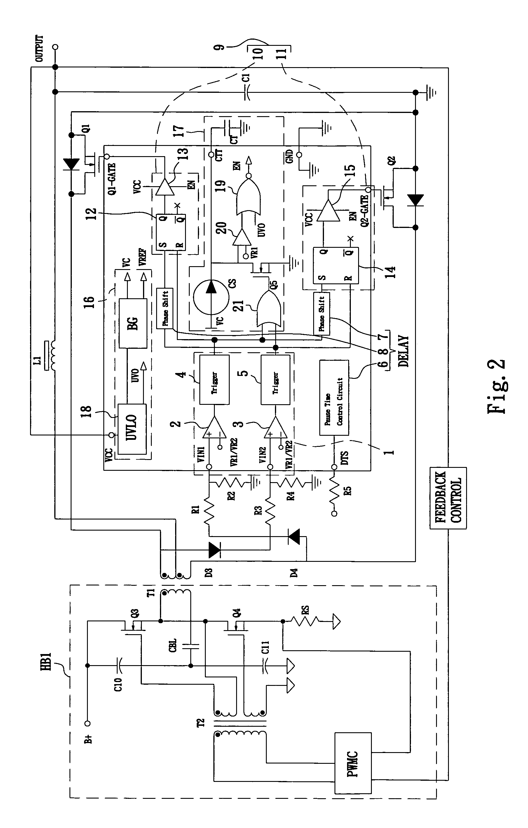
[0011]Referring to FIG. 2 for a schematic diagram of a rectifier control circuit used in a half-bridge circuit according to a preferred embodiment of the present invention, the half-bridge circuit installs a primary half-bridge circuit HB1 as shown in FIG. 1 at the primary winding of the main transformer T1, and the secondary winding of the primary transformer T1 uses a first current switch Q1 and a second current switch Q2 to substitute the two rectifier diode D2, D1, and the rest are identical to the secondary half-bridge circuit as shown in FIG. 1. In FIG. 2, the secondary winding of the main transformer T1 of the half-bridge circuit produces an input signal of a synchronous rectifier control circuit of the present invention. After the signal passes through the diode D3, D4, the voltage divider resistors R3, R4 and R1, R2 connected in series with each other produces a first input signal VIN1 and a second input signal VIN2.

[0012]In FIG. 2, a synchronous rectifier control circuit o...


PUM


Abstract

A synchronous rectifier control circuit improves energy conversion efficiency and uses a signal produced by a secondary winding of a transformer in a rectifier circuit to control a low-impedance and a low power consuming current switch such as a JFET and a MOSFET in a synchronous rectifier circuit to substitute a high power consuming diode rectification and appropriately rectify and extend the ON time of the current switch to prevent the positive and negative phases of the current switch to be turned on simultaneously, which will cause a large current to burn the current switch. The invention includes a protection circuit having an under voltage lock out circuit for an interrupt output function, so that if an insufficient instant power voltage occurs, the power is turned on or off to interrupt all outputs and force the current switch of the rectifier circuit to turn off, and prevent the output of an unstable working voltage of the rectifier control circuit or the abnormal operation of the current switch.

Description

FIELD OF THE INVENTION[0001]The present invention relates to a synchronous rectifier control circuit, and more particularly to a rectifier control circuit capable of controlling the pause time of a secondary output current switch of a transformer and improving the energy conversion efficiency.BACKGROUND OF THE INVENTION[0002]As the operations of internal components of most electronic appliances (such as television, stereo, computer, etc) require the use of a direct current power supply, and thus a rectifier is needed to convert the alternate current power into a direct current power of various different voltages and maximize the functions of these electronic appliances. The rectifier can be divided into a linear rectifier and a switching rectifier according to different circuit structures, and the simple linear rectifier is consisted of a transformer, a diode, and a capacitor filter, and its advantages include simple circuit, high stability, quick responses to pause, high reliabilit...

Claims


Application Information

Patent Timeline
IPC IPC(8): H02H7/125H02M3/335
CPCH02M3/33592Y02B70/1475Y02B70/10
Inventor HSU, DA-JINGZHU, YUN-KANG
Owner NIKO SEMICON
Why Eureka
Try Eureka