
Method for electrosurgical tissue treatment near a patient's heart

a tissue treatment and electrosurgical technology, applied in the field of electrosurgical tissue treatment near the heart of patients, can solve the problems of low volumetric ablation rate, high cost of laser equipment, and the own set of deficiencies of laser devices, so as to limit the depth of necrosis and limit tissue damage

Inactive Publication Date: 2007-05-15
ARTHROCARE
View PDF276 Cites 263 Cited by
  • Summary
  • Abstract
  • Description
  • Claims
  • Application Information

AI Technical Summary

Benefits of technology

The present invention provides a system and method for selectively applying electrical energy to structures within or on the surface of a patient's body for surgical procedures. The system includes an electrosurgical probe with an active electrode that can be positioned close to the target tissue to perform ablation or cutting procedures with limited damage to surrounding tissue. The method involves using a high frequency voltage to generate high voltage gradients in the vicinity of the probe tip, which creates an electric field high enough to break down the tissue through molecular dissociation or disintegration. The high frequency voltage applied between the active electrode and a return electrode creates an electric field that vaporizes the electrically conductive liquid and induces the discharge of highly energetic electrons and photons. This precise controlled ablation is at least partly caused by the high electric field generated around the tip of the active electrode. The system can be used in dry environments, such as oral or endoscopic procedures, and can also be used to remove tissue or perform dermatological procedures. The apparatus includes an electrosurgical probe with a shaft and at least one active electrode at or near the distal end.

Problems solved by technology

Despite these advantages, laser devices suffer from their own set of deficiencies.
In the first place, laser equipment can be very expensive because of the costs associated with the laser light sources.
Moreover, those lasers which permit acceptable depths of necrosis (such as eximer lasers, erbium:YAG lasers, and the like) provide a very low volumetric ablation rate, which is a particular disadvantage in cutting and ablation of fibrocartilage, articular cartilage, and meniscal tissue.
The holmium:YAG and Nd:YAG lasers provide much higher volumetric ablation rates, but are much less able to control depth of necrosis than are the slower laser devices.
The CO2 lasers provide high rate of ablation and low depth of tissue necrosis, but cannot operate in a liquid-filled cavity.

Method used


Image

  • Method for electrosurgical tissue treatment near a patient's heart
  • Method for electrosurgical tissue treatment near a patient's heart
  • Method for electrosurgical tissue treatment near a patient's heart

Examples


Embodiment Construction

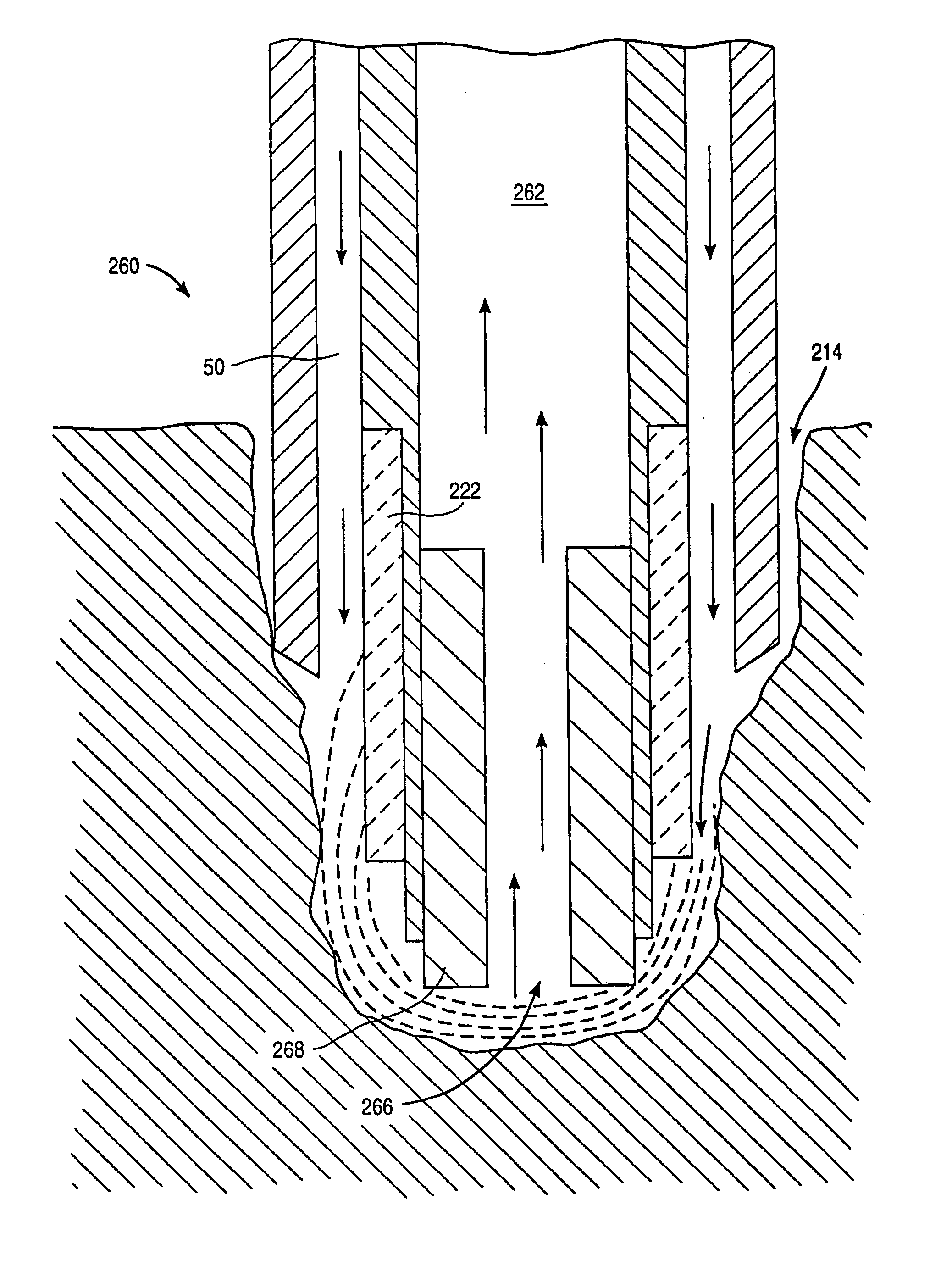
[0051]The present invention provides a system and method for selectively applying electrical energy to a target location within or on a patient's body, such as solid tissue or the like, particularly including gingival tissues and mucosal tissues located in the mouth or epidermal tissue on the outer skin. In addition, tissues which may be treated by the system and method of the present invention include tumors, abnormal tissues, and the like. The invention may also be used for canalizing or boring channels or holes through tissue, such as the ventricular wall during transmyocardial revascularization procedures. For convenience, the remaining disclosure will be directed specifically to the cutting, shaping or ablation of gingival or mucosal tissue in oral surgical procedures, the surface tissue ablation of the epidermis in dermatological procedures and the canalization of channels through the myocardium of the heart, but it will be appreciated that the system and method can be applied...


PUM

PropertyMeasurementUnit
electrical conductivityaaaaaaaaaa
depthaaaaaaaaaa
depthaaaaaaaaaa

Abstract

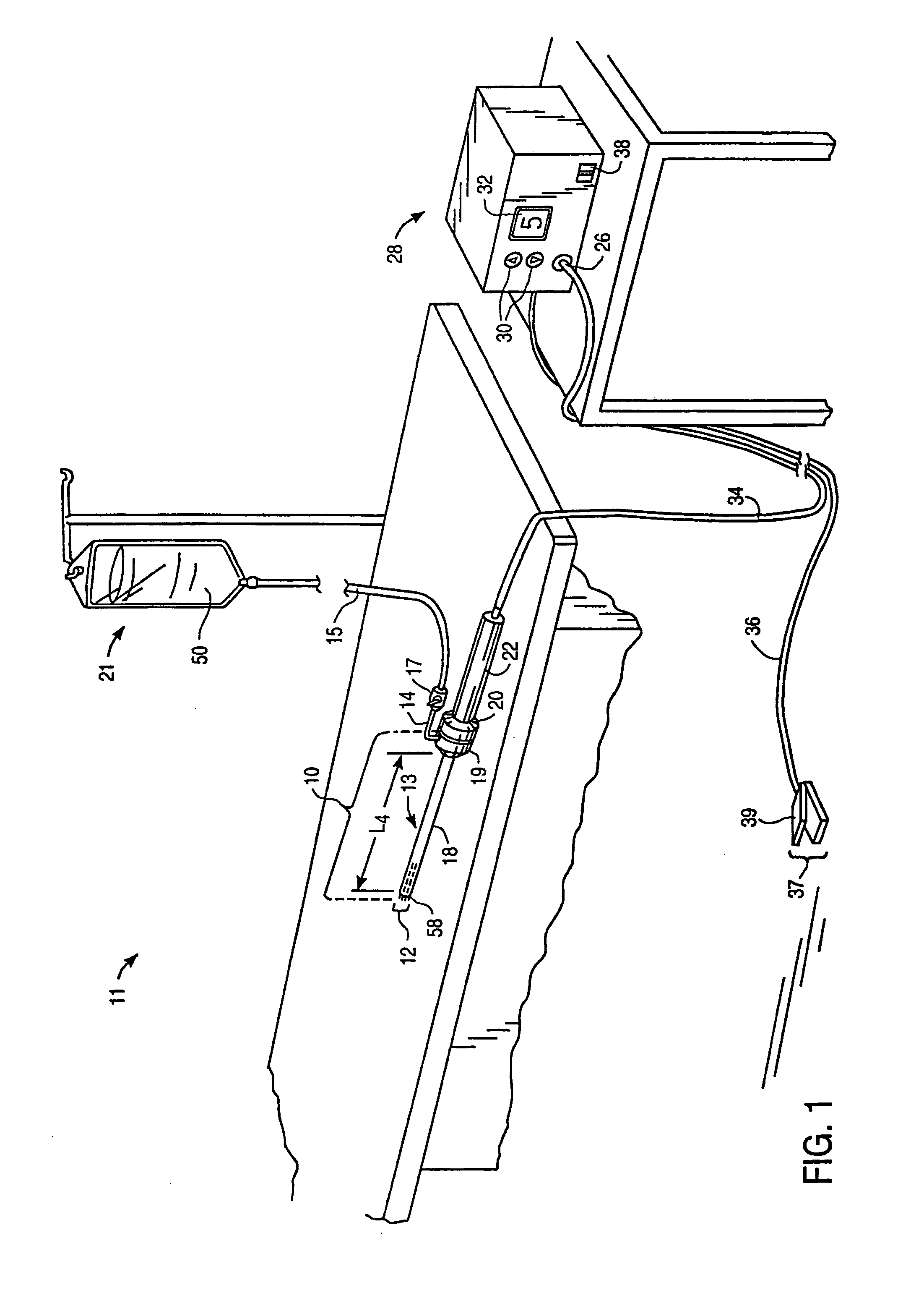
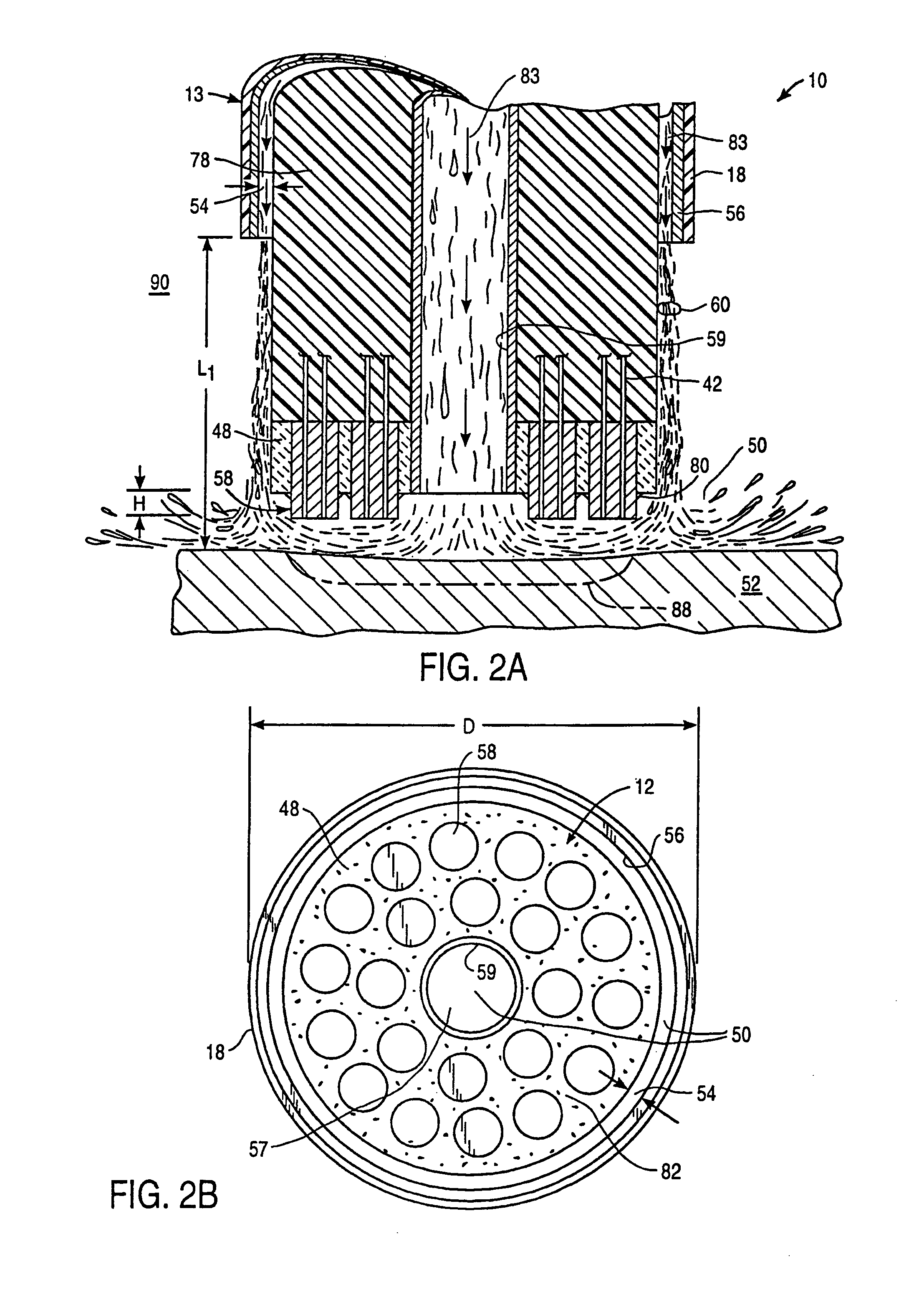
An electrosurgical probe (10) comprises a shaft (13) having an electrode array (58) at its distal end and a connector (19) at its proximal end for coupling the electrode array to a high frequency power supply (28). The shaft includes a return electrode (56) recessed from its distal end and enclosed within an insulating jacket (18). The return electrode defines an inner passage (83) electrically connected to both the return electrode and the electrode array for passage of an electrically conducting liquid (50). By applying high frequency voltage to the electrode array and the return electrode, the electrically conducting liquid generates a current flow path between the return electrode and the electrode array so that target tissue may be cut or ablated. The probe is particularly useful in dry environments, such as the mouth or abdominal cavity, because the electrically conducting liquid provides the necessary return current path between the active and return electrodes.

Description

[0001]The present invention is a continuation of U.S. Ser. No. 09 / 438,592, filed Nov. 12, 1999, now U.S. Pat. No. 6,632,220, and U.S. Ser. No. 09 / 438,592 is a divisional of U.S. Ser. No. 09 / 098,205, filed Jul. 27, 1998, now U.S. Pat. No. 6,224,592, and U.S. Ser. No. 09 / 098,205 is a divisional of Ser. No. 08 / 795,686, filed Feb. 5, 1997, now U.S. Pat. No. 5,871,469, and U.S. Ser. No. 08 / 795,686 is a divisional of U.S. Ser. No. 08 / 561,958, filed Nov. 22, 1995, now U.S. Pat. No. 5,697,882, and U.S. Ser. No. 08 / 561,958 is a continuation in part application of U.S. Ser. No. 08 / 485,219, filed Jun. 7, 1995, now U.S. Pat. No. 5,697,881, and U.S. Pat. No. 5,697,882 is a continuation in part application of U.S. Ser. No. 08 / 446,767, filed Jun. 2, 1995, now U.S. Pat. No. 5,697,909, the full disclosures of which are incorporated herein by reference.BACKGROUND OF THE INVENTION[0002]1. Field of the Invention[0003]The present invention relates generally to the field of electrosurgery and, more parti...

Claims


Application Information

Patent Timeline
Patent Type & Authority Patents(United States)
IPC IPC(8): A61B18/12A61B18/14A61B17/00A61B17/22A61B18/00A61B19/00A61F2/02A61F2/06A61F2/84A61M1/00A61M3/02A61M25/01
CPCA61B18/12A61B18/1206A61B18/1402A61B18/148A61B18/1482A61B18/1485A61B18/149A61B18/1492A61M25/0133A61B18/042A61B2017/00026A61B2017/00084A61B2017/00097A61B2017/00101A61B2017/00106A61B2017/00247A61B2017/00292A61B2017/003A61B2017/22001A61B2017/22038A61B2018/00029A61B2018/00083A61B2018/00119A61B2018/0016A61B2018/00178A61B2018/00196A61B2018/00327A61B2018/00392A61B2018/0047A61B2018/00476A61B2018/00505A61B2018/00577A61B2018/00583A61B2018/00601A61B2018/00642A61B2018/0066A61B2018/00678A61B2018/00702A61B2018/00726A61B2018/00738A61B2018/00755A61B2018/00761A61B2018/00791A61B2018/00797A61B2018/00821A61B2018/00827A61B2018/00875A61B2018/00886A61B2018/00982A61B2018/1213A61B2018/124A61B2018/1246A61B2018/1253A61B2018/126A61B2018/1273A61B2018/1407A61B2018/1467A61B2018/1472A61B2018/162A61B2018/165A61B2019/5276A61B2019/5278A61B2218/002A61B2218/007A61F2/2493A61F2/95A61M25/0147A61M25/0158A61B2090/3782A61B2090/378
Inventor EGGERS, PHILIP E.THAPLIYAL, HIRA V.
Owner ARTHROCARE
Learn More