Digital data transmitter

a digital transmission and data transmitter technology, applied in the direction of restoring means or bias distort correction, line-faulk/interference reduction, baseband system details, etc., can solve the problems of reducing the reliability of digital transmission, reducing the product cost of filters, and reducing the product cost of filters. , to achieve the effect of eliminating almost all electromagnetic noise, reducing the product cost of filters, and eliminating noise caused by differential driver distortion

Inactive Publication Date: 2007-05-15
PANASONIC CORP
View PDF30 Cites 13 Cited by
  • Summary
  • Abstract
  • Description
  • Claims
  • Application Information

AI Technical Summary

Benefits of technology

[0045]According to another embodiment of the present invention, wherein there is provided a data transmission apparatus including: a data coding means for converting digital data into a signal level corresponding to a symbol that is assigned to the digital data in each symbol cycle as a prescribed unit cycle; a first digital filter that has a first sampling cycle that is shorter than a unit cycle of a signal level string which has been coded by the data coding means, and allows only predetermined frequencies to pass; a D/A conversion means for converting the digital data stream that has passed through the digital filter, into an analog signal; a first low-pass filter for eliminating folding distortion of the first digital filter from the analog signal obtained by the D/A conversion means, which distortion is decided in the first sampling cycle; a differential driver for converting an output of the low-pass filter, into two signals having opposite polarities relative to a predetermined reference potential, and differentially outputting the two signals; a second low-pass filter for eliminating a predetermined frequency band from each of the signals which are outputted from the differential driver; and a common mode choke coil for eliminating common mode noises and outputting

Problems solved by technology

The frequencies of these signals are so high that emitted noises cause large problems when these signals are transmitted through copper wires or the like.
For example, when such apparatus is mounted on a motor vehicle or the like, emitted noises may cause malfunctions of other electronic equipment that is mounted on the motor vehicle.
One of factors that reduce the reliability in the digital transmission is that when the transmission signal constantly takes the same signal level, synchronization of symbol timing cannot be obtained at the receiving end.
In addition, the optical fiber has a problem in its strength, such as limitation in the bend angle of the cable, so that the application range thereof is limited.
Furthermore, according to the method in which signals having opposite polarities are passed through a twisted pair cable, when the signals to be transmitted include higher frequency components, the signals which flow through two transmission wires of the cable do not always cancel each other out due to slight asymmetry between the two transmission wires, whereby noises occur unfavorably, so that a sufficient reduction in noises cannot be obtained in the case of high-speed data transmission.
However, it is difficult to give steep high-band cut-off characteristics to a filter composed of analog elements, without loosing digit

Method used


Image

  • Digital data transmitter
  • Digital data transmitter
  • Digital data transmitter

Examples


embodiment 1

[Embodiment 1]

[0060]Initially, a digital data transmission apparatus and a data transmission apparatus will be described as a first embodiment, with reference to the drawings.

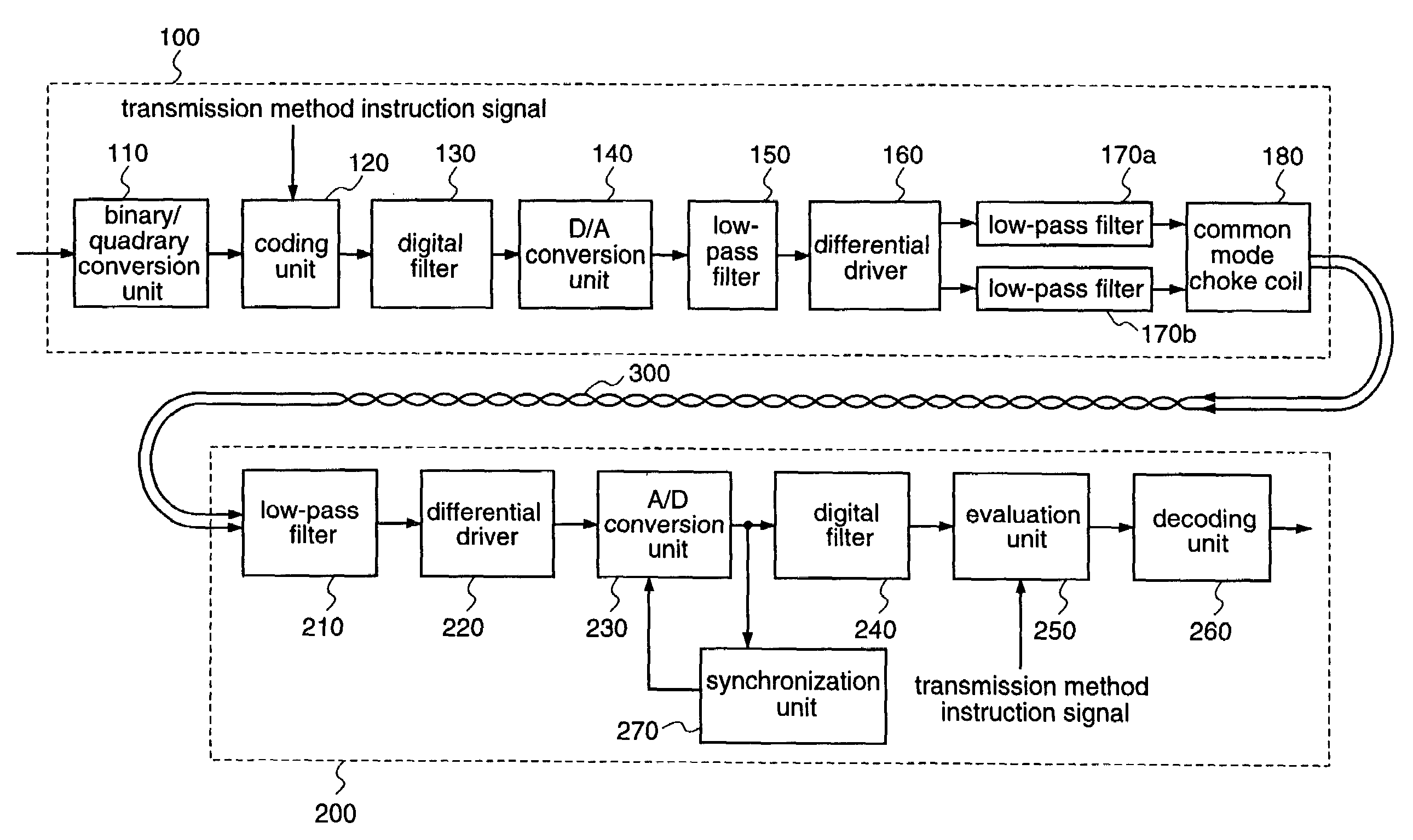
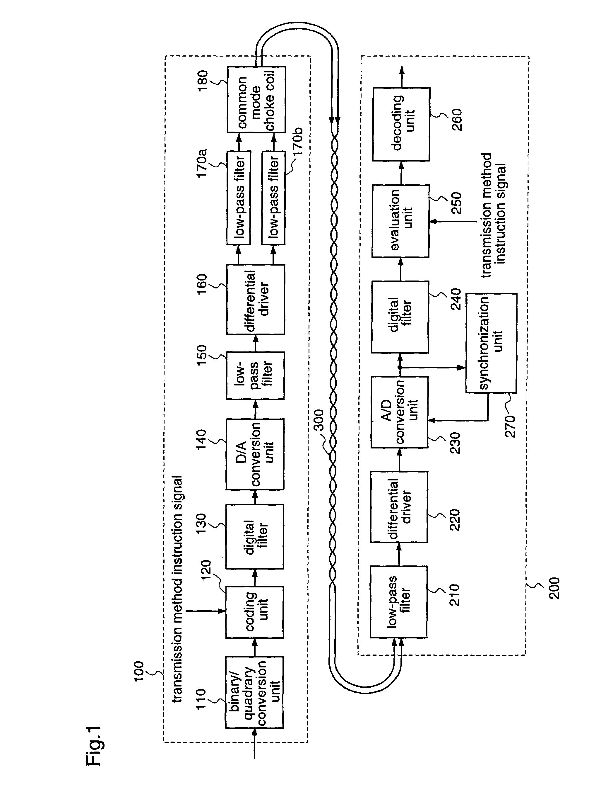
[0061]FIG. 1 is a block diagram illustrating a structure of a digital data transmission apparatus according to the first embodiment.

[0062]As shown in FIG. 1, the digital data transmission apparatus according to the first embodiment includes a transmitting end 100 for transmitting data, and a receiving end 200 for receiving the data transmitted from the transmitting end 100, which are connected with each other through a twisted pair cable 300.

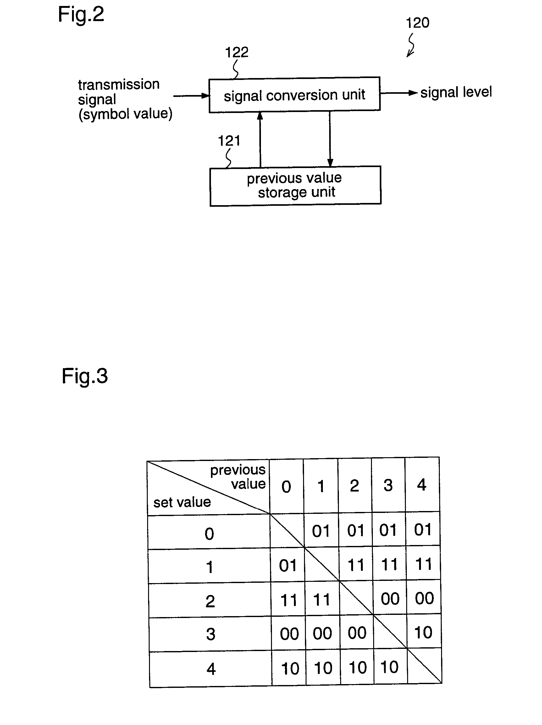
[0063]The transmitting end 100 includes a binary-to-quadrary conversion unit 110 for converting a 1-bit data stream into a 2-bit (four-valued) data stream; a coding unit 120 for mapping 2-bit data that is obtained by the binary / quadrary conversion unit to a predetermined signal level to be coded; a digital filter 130 that allows a band of frequency components corresponding ...


PUM


Abstract

A digital data transmission apparatus includes a transmitting end (100) that includes: a binary/quadrary conversion unit (110) for converting a data stream; a coding unit (120) for mapping converted data to be coded; a digital filter (130); a D/A conversion unit (140); a low-pass filter (150) for attenuating noises which are caused by folding distortion; a differential driver (160); low-pass filters (170a) and (170b) for eliminating noises from differentially outputted signals; and a common mode choke coil (180) for eliminating common mode noises and outputting a resultant signal to a twisted pair cable (300), and a receiving end (200) that includes: a low-pass filter (210) for eliminating noises from the twisted pair cable; a receiver (220); an A/D conversion unit (230); a digital filter (240); an evaluation unit (250) for evaluating a signal level of a received signal; a decoding unit (260) for decoding the signal level into received data; and a synchronization unit (270) for generating a clock.

Description

TECHNICAL FIELD[0001]The present invention relates to a digital data transmission apparatus and, more particularly, to a digital data transmission apparatus that reduces emission of noises by a digital filter.BACKGROUND ART[0002]Some conventional data transmission apparatuses convert digital data into signal levels of electric signals or optical signals to be transmitted. The transmission rates have been increased through the years and, recently, some apparatuses transmit large amounts of data, such as video signals, at transmission rates of several tens of megabits / sec. The frequencies of these signals are so high that emitted noises cause large problems when these signals are transmitted through copper wires or the like.[0003]For example, when such apparatus is mounted on a motor vehicle or the like, emitted noises may cause malfunctions of other electronic equipment that is mounted on the motor vehicle. Accordingly, there is a need to make the apparatus hardly emit noises when mo...

Claims


Application Information

Patent Timeline
IPC IPC(8): H04L27/00H04L25/06H04L25/08H04L25/49
CPCH04L25/062H04L25/066H04L25/085H04L25/4919
Inventor KATTA, NOBORUMIZUGUCHI, YUJISAKAI, TAKAHISAKAWADA, HIROTSUGUKUROSAKI, TOSHIHIKO
Owner PANASONIC CORP
Why Eureka
Try Eureka