UV photochemical option for closed cycle decomposition of hydrogen sulfide

a photochemical option and closed cycle technology, applied in the direction of multi-stage water/sewage treatment, separation process, nature of treatment water, etc., can solve the problems of hsub>2/sub>s gas in the refinery

Inactive Publication Date: 2007-05-22
UNIV OF CENT FLORIDA RES FOUND INC +1
View PDF20 Cites 46 Cited by
  • Summary
  • Abstract
  • Description
  • Claims
  • Application Information

AI Technical Summary

Benefits of technology

[0017]The following chemical process shows the effects of combining sulfur recovery and scrubber units, utilizing the acid properties of H2S itself to decompose polysulfide ions and free the elemental sulfur.

Problems solved by technology

The problem is what do the refineries do with the H2S gas, which is a noxious poisonous gas that cannot be released into the atmosphere.

Method used


Image

  • UV photochemical option for closed cycle decomposition of hydrogen sulfide
  • UV photochemical option for closed cycle decomposition of hydrogen sulfide
  • UV photochemical option for closed cycle decomposition of hydrogen sulfide

Examples


first preferred embodiment

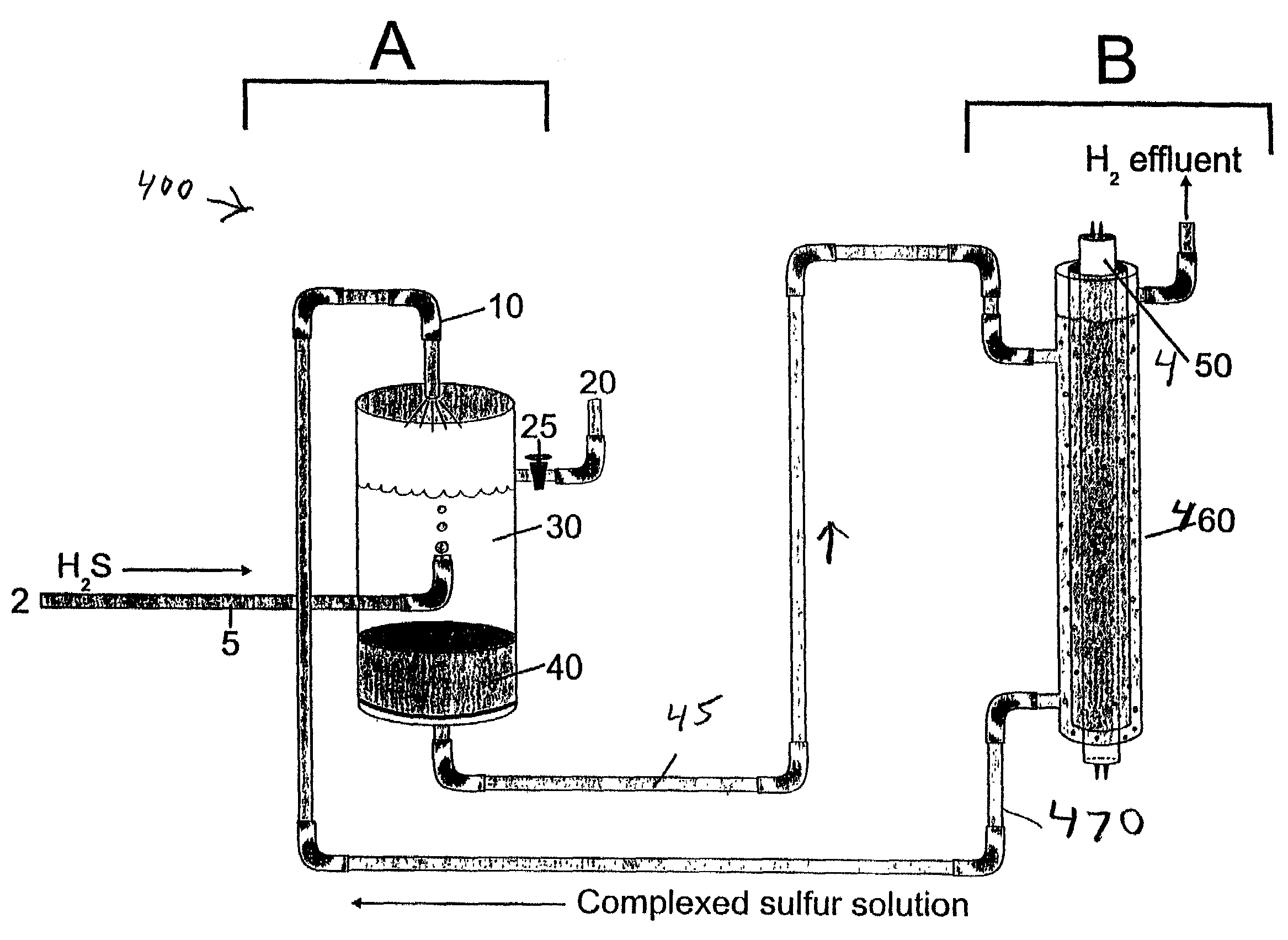
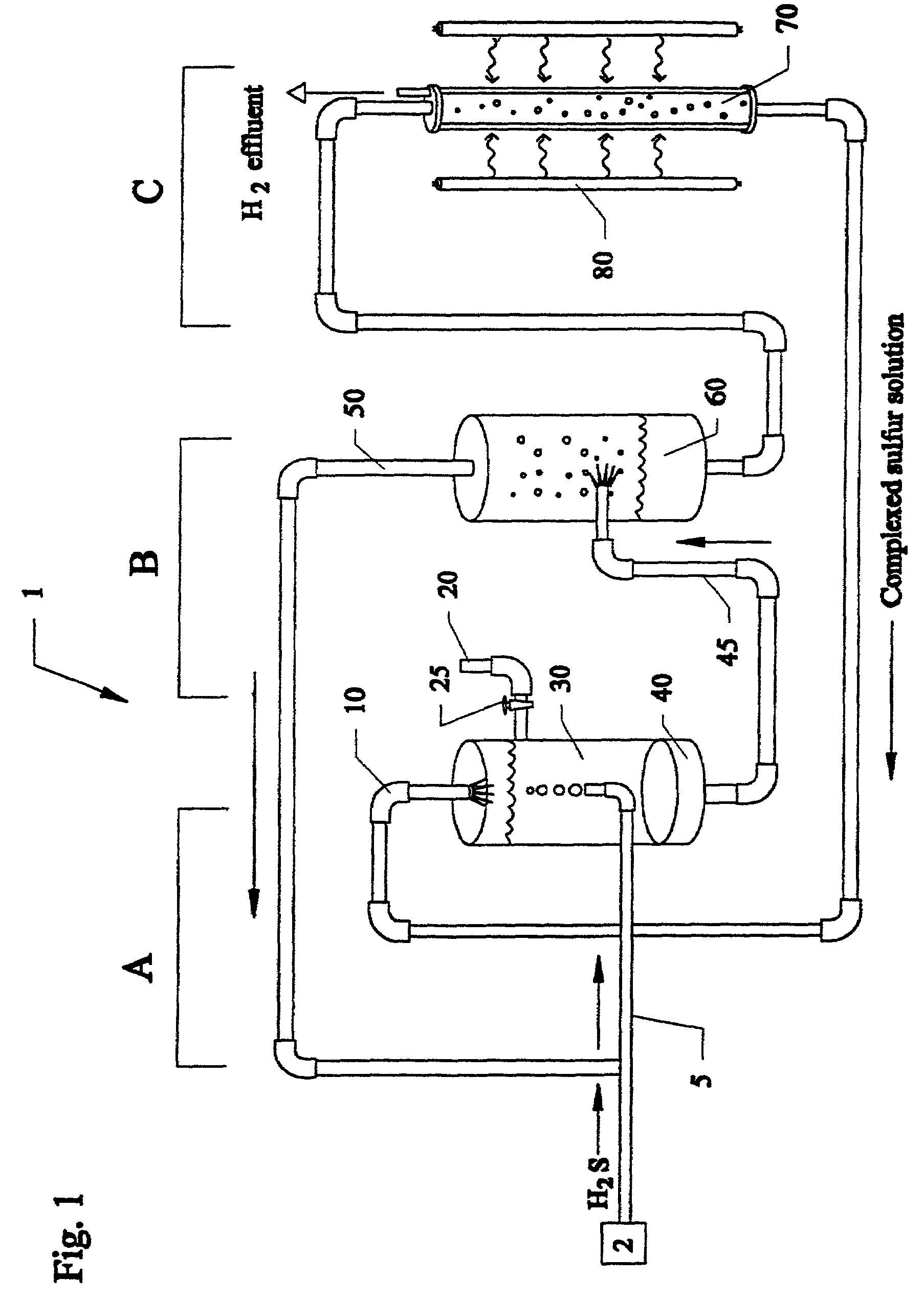
[0027]FIG. 1 is a layout system 1 of a first preferred embodiment of using a photoelectrochemical particle(PEP) process for H2S decomposition for sulfur recovery. The first preferred embodiment is described in detail in reference to prior U.S. application Ser. No. 09 / 784,393 filed Feb. 15, 2001, which is a Divisional Application of Ser. No. 09 / 375,967 filed Aug. 17, 1999, now U.S. Pat. No. 6,248,218, which claims the benefit of priority of U.S. Provisional Application 60 / 126,036 filed on Mar. 25, 1999, by the same assignees, all of which are incorporated by reference.

[0028]The system 1 consists of three major units: A, the scrubber and filtration apparatus; B, an outgassing unit such as an H2S stripper, and the like; and C, the photoreactor. The scrubber used would be akin to a wet scrubber used in gas cleaning applications such as but not limited to the scrubber unit used in U.S. Pat. No. 5,211,923 to Harkness et al., which is incorporated by reference. Hydrogen sulfide H2S, coming...

second preferred embodiment

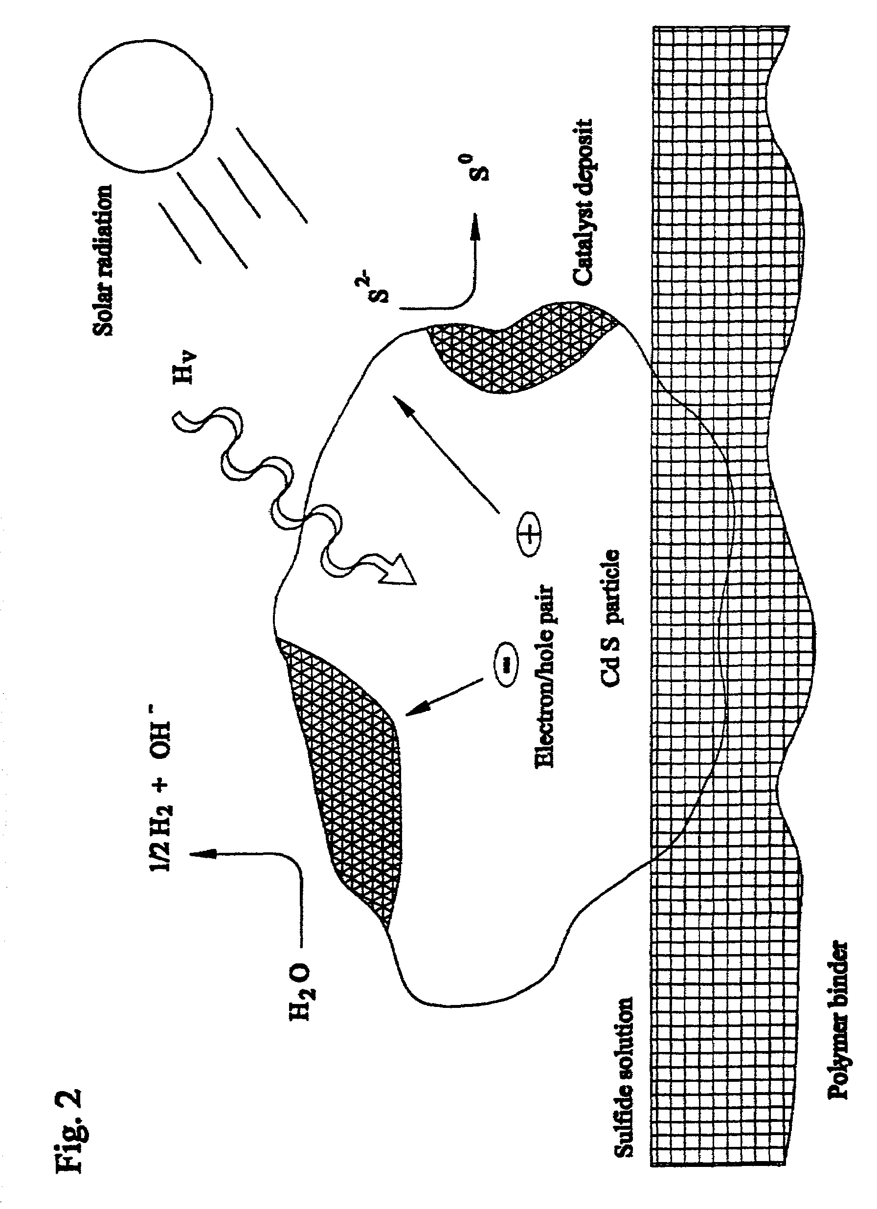
[0036]In this embodiment, the final stage of the first preferred embodiment is eliminated, so that an ultraviolet source emitting at approximately 254 nm from a low-pressure mercury lamp illuminates the alkaline sulfide solution alone with no catalyst, instead of using a photocatalyst and a reactor that is subjected to a visible wavelength lamp at approximately 450 to approximately 500 nm. Lamp can be but is not limited to cadmium line emission lamp, a super actinic mercury lamp, and the like. Unlike the first embodiment, the second embodiment is limited to using artificially created ultraviolet radiation.

[0037]Other than not being able to use sunlight, the second preferred embodiment has most of the basic advantages of the first preferred embodiment and many additional advantages. For example, avoiding the use of a photocatalyst removes the cost requirement of having a photocatalyst. Thus, the second embodiment is less expensive than the first embodiment. Additionally, the lack of ...


PUM

PropertyMeasurementUnit
wavelengthaaaaaaaaaa
wavelength rangeaaaaaaaaaa
maximum wavelength rangeaaaaaaaaaa

Abstract

Methods and systems for separating hydrogen and sulfur from hydrogen sulfide(H2S) gas. Hydrogen sulfide(H2S) gas is passed into a scrubber and filtration unit with polysulfide solution. Interaction frees elemental sulfur which is filtered, excess continues to a stripper unit where the excess H2S is removed. The excess H2S returns to the scrubber and filtration unit, while the sulfide solution passes into a photoreactor containing a photocatalyst and a light source. The sulfide solution is oxidatively converted to elemental sulfur and complexed with excess sulfide ion to make polysulfide ion, while water is reduced to hydrogen. Hydrogen is released, while the polysulfide solution is fed back to the scrubber unit where the system operation repeats. In a second embodiment, the photocatalyst is eliminated, and the hydrogen sulfide solution is directly illuminated with ultraviolet radiation with a light source such as a low pressure mercury lamp operating at approximately 254 nm.

Description

[0001]This invention relates to sulfur recovery from oil and gas refinery waste streams, and in particular to a method and apparatus for a closed cycle system for the decomposition of hydrogen sulfide using an ultraviolet source to directly illuminate an alkaline sulfide solution to yield both sulfur and hydrogen which can be later sold or used internally at a refinery and is a Continuation-In-Part of U.S. application Ser. No. 09 / 784,393 filed Feb. 15, 2001 now U.S. Pat. No. 6,572,829, which is a Divisional application of Ser. No. 09 / 375,967 filed Aug. 17, 1999, now U.S. Pat. No. 6,248,218, which claims the benefit of priority of U.S. Provisional Application 60 / 126,036 filed on Mar. 25, 1999, by the same assignees.BACKGROUND AND PRIOR ART[0002]Oil refineries typically process crude oil from the ground which contains unusable organic sulfur, the latter of which must be separated from the crude oil in order to allow the oil to become a useful product. Typically, the crude oil is treat...

Claims


Application Information

Patent Timeline
Patent Type & Authority Patents(United States)
IPC IPC(8): B01J19/08
CPCB01D53/52B01J19/123C10G70/00C10G70/06B01D53/77B01D2255/802B01D2257/304B01D2259/804B01J2219/0884C02F1/32C02F1/725C02F9/00C02F2103/10C02F2103/18C02F2103/28C02F2103/365C02F2301/046C02F1/70C02F1/72Y02W10/37
Inventor HUANG, CUNPINGLINKOUS, CLOVIS A.
Owner UNIV OF CENT FLORIDA RES FOUND INC
Why Eureka
Try Eureka