
Adsorption membranes, method of producing same and equipment, including the adsorption membranes

a technology of adsorption membrane and adsorption membrane, which is applied in the field of adsorption membrane, can solve the problems of negative analytical effect, unavoidable deleterious edge effects, and complex adsorption with the corresponding adsorbent, and achieve the effect of high separation capacity

Active Publication Date: 2007-05-29
SARTORIUS STEDIM BIOTECH GMBH
View PDF13 Cites 5 Cited by
  • Summary
  • Abstract
  • Description
  • Claims
  • Application Information

AI Technical Summary

Benefits of technology

[0018]Therefore, the object of the present invention is to provide adsorption membranes having a high separation capacity with regard to samples that are to be purified and / or concentrated while avoiding the problems described above. Additional objects of the present invention include providing a method for producing the adsorption membranes and equipment, including said adsorption membranes.SUMMARY OF THE INVENTION
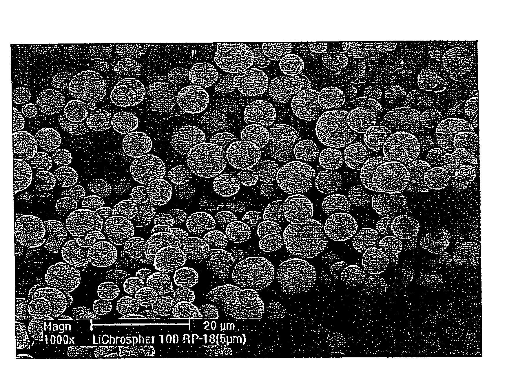
[0029]The inventive adsorption membranes thus have relatively coarse continuous pores, which permit high hydraulic permeabilities as well as regions of fine pores which are in enclosed particulate porous adsorbents and ensure high capacities. The particulate adsorbents used may be perfusion matrices according to this invention to improve the kinetic properties and / or may have a very small size which has as little deleterious effect on their hydraulic permeability as does an irregular particle shape, which has the economic advantages mentioned above.
[0037]In addition, in the inventive method for producing an adsorption membrane, measures may advantageously be taken so that the possibility of contact between the adsorbent particle surface area in a finished inventive adsorption membrane and the liquid to be treated, containing an adsorbate, for example, is not impaired after embedding the adsorbent particles in the membrane. This would be the case, for example, if essential parts of the adsorbent particle surface or its pore volume were blocked by the polymer carrier. This can be prevented to advantage in the inventive method by the fact that attractive forces are ruled out between these polymer molecules and the adsorbent particles in the stages of the production process in which the polymer molecules are freely mobile, and this is preferably achieved by the fact that the polymer molecules and the adsorbent particles have the same electric charges.
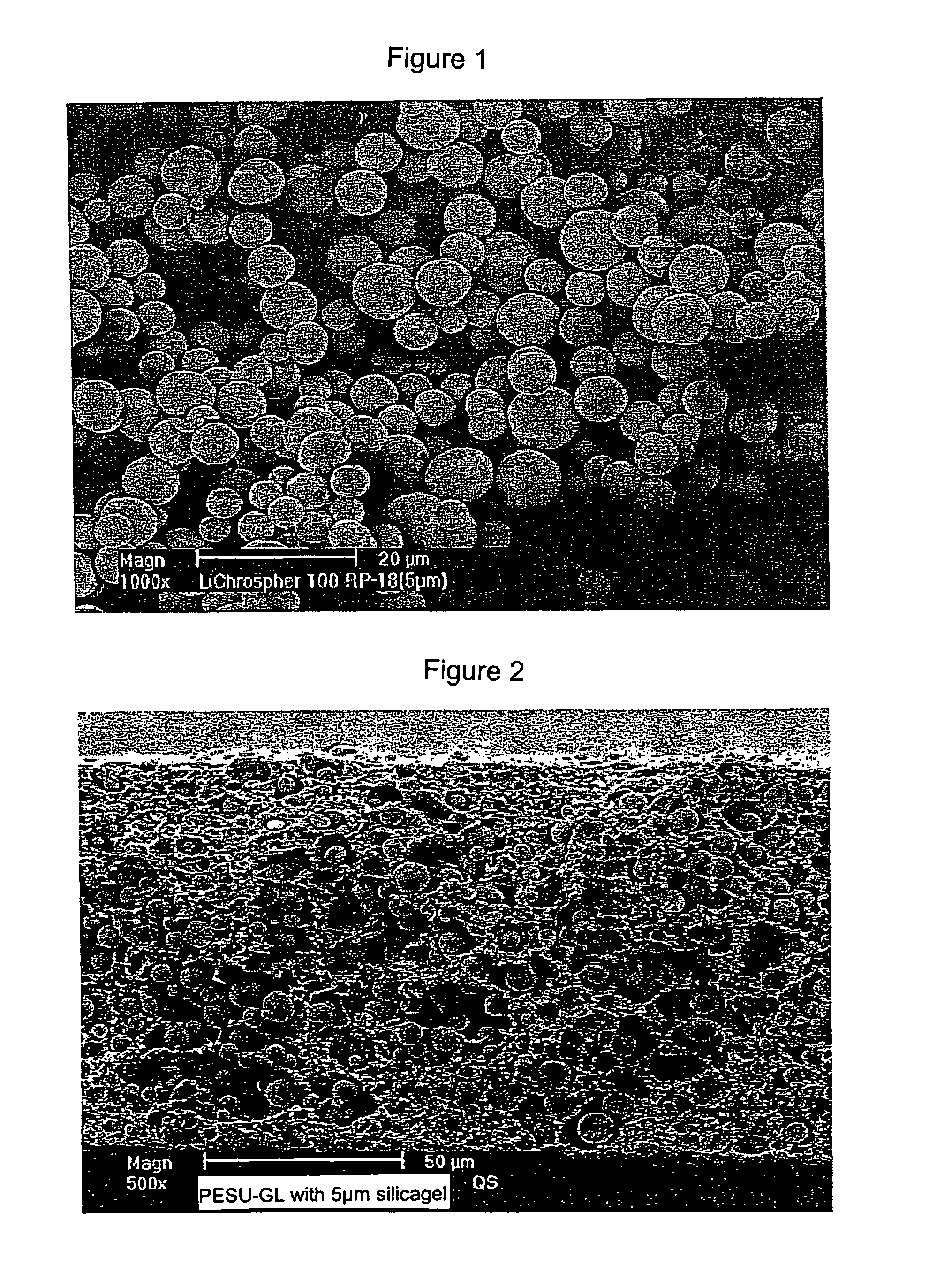
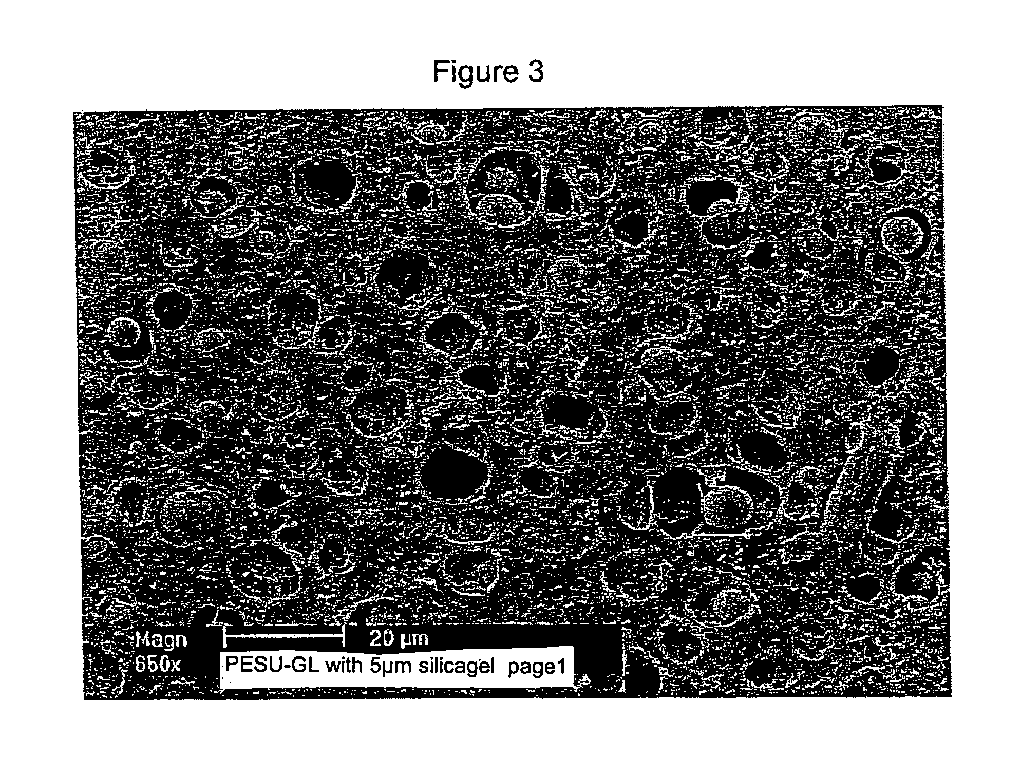
[0038]In the inventive method for producing an adsorption membrane, the controlled phase reversal is achieved through the targeted adjustment of the ratio of precipitation agent and solvent for the polymer used, with water being a conventional precipitation agent. This avoids a sudden phase reversal occurring when using a pure precipitation agent such as water, which would result in a skin being formed on the resulting membrane which would have only a few very small pores or none at all and an underlying asymmetrical pore structure is formed in the corresponding membrane. Accordingly, an adsorption membrane produced by the inventive method does not have any skin and it also has a symmetrical pore structure as illustrated in FIG. 2 and FIG. 3, for example.

Problems solved by technology

Because of the sensitivity of these analytical methods, even small quantities of the aforementioned secondary constituents present in a sample to be analyzed can have a very negative effect on the analytical results.
1. Loading of an adsorber with the corresponding adsorbent is complicated because irregularities, channeling and the like must be prevented. There are also unavoidable deleterious edge effects between the adsorbent and the adsorber housing.
2. There is an antagonism between the pressure drop and the transport kinetics such that the latter is facilitated by smaller particle sizes but the pressure drop is increased at the same time. Particles down to 1 μm in diameter, optionally even in a nonporous form, are therefore above all used for analytical separations in so-called HPLC (high performance liquid chromatography). For applications on an industrial scale, however, relatively large particles must be used in order to limit the pressure drop. The unfavorable transport kinetics in this case can be improved only slightly by using particulate perfusion matrices. In addition, a low pressure drop can be achieved only with approximately monodisperse spherical particles but these are much more expensive to produce in comparison with irregularly shaped particles.
However, the production process does not offer good scale-up opportunities any better than those proposed by Svec (T. B. Tennikova et al., Journal of Chromatography, 555, (1991), pages 97 to 107) based on polymerization of ethylenically unsaturated monomers to form structures of a suitable shape and porosity.
This latter process is limited by the impossibility of removing the reaction heat generated with larger units.
1. Most of the polymers suitable for producing them such as polysulfones, polyvinyl chloride (PVC), etc. do not have an adequate density of suitable anchor groups and they have a rather marked tendency to nonspecific adsorption.
2. In the pore size range which ensures a high hydraulic permeability, there is not a sufficient specific surface area to achieve high capacities.
3. The chemical conversion of sheet materials necessitates mechanically complex equipment for technical implementation and requires the use of large volumes of reaction media.
It follows from this that they become clogged sooner or later due to the particulate impurities that are always present in real media when these membranes are used in membrane chromatography, and this blockage cannot be reversed even by reversing the direction of flow (“backwashing”).
Furthermore, the silica gel particles whose adsorptive properties have been modified according to the company brochure mentioned above and which are used in the membrane are not porous, which results in a low adsorption capacity.
As with the product mentioned above, this has the abovementioned disadvantages of chemical reactions on the membrane sheet.
For example, U.S. Pat. No. 4,373,519 proposes the use of PTFE membranes containing dextran particles for wound closure but they are not suitable as adsorption membranes because of their lack of adsorption capacity.
The presence of a skin, in particular when it has large openings, is a disadvantage in adsorption membranes because in those areas where the skin occurs, the hydraulic permeability is reduced, whereas it is not reduced in the area of the openings.
This results in irregular flow velocities through the membrane over the membrane area, which results in premature exhaustion of the adsorption capacity in regions of high hydraulic permeability and there is a flow-through of the adsorbate before exhausting the capacity of the entire membrane.

Method used


Image

  • Adsorption membranes, method of producing same and equipment, including the adsorption membranes
  • Adsorption membranes, method of producing same and equipment, including the adsorption membranes
  • Adsorption membranes, method of producing same and equipment, including the adsorption membranes

Examples


example 1

[0052]Production of a microporous polyether sulfone membrane loaded with hydrophobic ligands containing silica particles as filler

[0053]A casting solution having the following composition was prepared: 81.8% 2-pyrrolidone, 11.5% polyether sulfone E6020, 4.7% water and 2% glycerol (86.5%) were dissolved while stirring at 50° C. for eight hours. A mixture of 90% of this solution and 10% of a silicic acid material containing C18 ligands from the company Merck in Darmstadt (order no. 1.116177, lot L448077 234) was prepared by agitating at 600 rpm for 30 minutes at 30° C. using a propeller stirrer. In addition, this casting solution was degassed for 24 hours in a vacuum of 150 mbar. This degassed casting solution was shaped to yield a microporous membrane with a thickness of 150 μm by means of a drawing device in an aqueous precipitation bath. After obtaining approx. 1000 cm2 of a microporous structure, the piece of membrane was washed with PBS and stored at 4° C. in PBS.

example 2

[0054]Manufacturing centrifugal units with the inventive membrane from Example 1

[0055]Filter rounds 3 mm in diameter made of an inventive membrane from Example 1 were installed in centrifugal units developed as experimental products under the name Microspin Columns by the company Vivascience AG, Hannover and were secured by a well-fitting insert. The units had an effective filter area of 3.1 mm2. The units are referred to below as RP-18 Microspins.

[0056]Example 3

[0057]Concentrating bioactive peptides with RP-18 Microspins

[0058]The following bioactive peptides were obtained from SIGMA Deisenhofen:

[0059]Bradykinin fragments 1–7 (order no. B-1651, lot 41K13641)

[0060]Angiotensin II fragments 1–7 (order no. A-9202, lot 21K5122)

[0061]Angiotensin II (order no. A-9525, lot 31K51144)

[0062]These are listed in tabular form in Table 1.

[0063]

TABLE 1Molecular weights and amounts of bioactive peptides used.DesignationMWTotal Amount1:10Bradykinin 757 Da*12 pg16 pmol1.2 pg1.6 pmolfragments 1–7Angiot...


PUM

PropertyMeasurementUnit
thicknessaaaaaaaaaa
diameteraaaaaaaaaa
particle sizesaaaaaaaaaa

Abstract

The present invention relates to adsorption membranes, comprising microporous polymer membranes into which are incorporated porous silicon dioxide particles modified with hydrocarbon ligands having 2 to 24 carbon atoms as adsorbent particles. Furthermore, the present invention relates to a method of producing the inventive adsorption membranes as well as devices which comprise the inventive adsorption membranes.

Description

FIELD AND BACKGROUND OF THE INVENTION[0001]The present invention relates to adsorption membranes, including microporous polymer membranes with silicon dioxide particles modified with hydrocarbon ligands having 2 to 24 carbon atoms embedded in them as adsorbent particles. Furthermore, the present invention also relates to a method of producing the inventive adsorption membranes as well as devices which include the adsorption membranes.[0002]In the past, a variety of analytical methods have been developed which necessitate removing various substances such as solvents, low molecular ions and impurities from solutions such as peptide solutions which contain macromolecules in order to obtain sufficiently concentrated and purified samples for the respective analysis. Because of the sensitivity of these analytical methods, even small quantities of the aforementioned secondary constituents present in a sample to be analyzed can have a very negative effect on the analytical results.[0003]One...

Claims


Application Information

Patent Timeline
Patent Type & Authority Patents(United States)
IPC IPC(8): B01D71/04B01D15/00B01D71/06H01M2/14B01D61/00B01D67/00B01D69/14B01J20/10B01J20/28B01L3/00C08J5/22
CPCB01D61/00B01D67/0011B01D69/141B01J20/103B01J20/28004B01J20/28019B01J20/28033B01J20/28052B01J20/28078B01J20/28097B01J20/3242C08J5/2275B01L3/50255B01D2325/04B01D2325/12C08J2339/06C08J2371/12B01D69/1411
Inventor DEMMER, WOLFGANGFISCHER-FRUEHHOLZ, STEFANKOCOUREK, ANDREASNUSBAUMER, DIETMARWUENN, EBERHARD
Owner SARTORIUS STEDIM BIOTECH GMBH
Learn More