Microcavity biosensor and uses thereof

Inactive Publication Date: 2007-06-05
UNIVERSITY OF ROCHESTER
View PDF7 Cites 44 Cited by
  • Summary
  • Abstract
  • Description
  • Claims
  • Application Information

AI Technical Summary

Benefits of technology

[0010]A third aspect of the present invention relates to a method of making a biological sensor which detects a target molecule. This method includes: providing a primed porous semiconductor structure including a central layer interposed between upper and lower layers, each of the upper and lower layers including strata of alternating porosity, and a coupling agent bound to the semiconductor structure; and exposing the primed porous semiconductor structure to a probe molecule including (i) one or more semiconductor structure-binding groups and (ii) one or more target-binding groups that bind to a target molecule, said exposing being carried out under conditions effective to bind the probe molecule to the primed porous semiconductor structure via the coupling agent or directly to the semiconductor structure upon displacement of the coupling agent, with the one or more target-binding groups remaining available for binding to the target molecule.
[0011]A fourth aspect of the present invention relates to a method of detecting a target molecule which includes: exposing a biological sensor of the present invention to a sample under conditions effective to allow binding of a target molecule in the sample to the one or more probes of the biological sensor; and determining whether the biological sensor emits a photoluminescent emission pattern which shifts following said exposing, whereby a shifted photoluminescent emission pattern indicates the presence of the target molecule in the sample.
[0012]A fifth aspect of the present invention relates to a method of detecting the presence of Gram negative bacteria in

Problems solved by technology

Qualitative analysis of such analytes is generally limited to the higher concentration levels, whereas quantitative analysis usually requires labeling with a radioisotope or fluorescent reagent.
Such procedures are time consuming

Method used


Image

  • Microcavity biosensor and uses thereof
  • Microcavity biosensor and uses thereof
  • Microcavity biosensor and uses thereof

Examples


example 1

Synthesis of Porous Silicon Microcavity

[0069]Porous silicon samples are produced electrochemically with computer control. This allows precise control of the current density and switching times necessary in the fabrication of multilayer structures and assures maximum reproducibility.

[0070]The multilayer structure is created using a periodic current density square pulse during the electrochemical dissolution process. The dissolution of the silicon atoms is mainly restricted to a region next to the substrate, therefore the porous layer first formed remains intact throughout subsequent etching. By varying the current density during the etch, it is possible to change the porosity at the silicon / electrolyte interface.

[0071]Porous silicon multilayer mirrors and microcavity resonators are electrochemically formed by anodic etching in a hydrofluoric electrolyte. Table 1 below details the experimental conditions used in the formation of porous silicon 10 multilayer mirrors.

[0072]

TABLE 1Porous...

example 2

Preparation of DNA Binding Sensor

[0076]Using a porous silicon microcavity structure prepared according to Example 1, a DNA binding sensor was prepared by attaching a DNA probe to the porous silicon microcavity.

[0077]Silanization of the porous silicon microcavity was achieved by its incubation in a 5% solution of 3-glycidoxypropyl trimethoxy silane in water / ethanol (1:1) for 14 hours. Silane solution was then drained off, and the silanized device washing repeatedly with glass-distilled, deionized water.

[0078]The silanized porous silicon microcavity structures were exposed to a 24-mer DNA molecule according to SEQ ID No: I as follows:

tagctatgga attcctcgta ggca 24

[0079]The 24-mer DNA molecules covalently bond to the silanized surface, where they become immobilized. The nucleophilic amine group, attached at the 3′ end of the DNA strand, attacks the epoxide ring of the silane. The porous silicon—DNA samples are initially placed in a constant temperature water bath where they are incubate...

example 3

Binding Complementary DNA with DNA Binding Sensor

[0081]A DNA binding sensor of Example 2 was used to bind a strand of DNA complementary to the probe. The complementary 22-mer DNA molecule has a nucleotide sequence according to SEQ ID No: 2 as follows:

gcctacgagg aattccatag ct 22

[0082]The sensing probes of single stranded DNA molecules seek out only their complement in a complex mixture of DNA containing a large number of other nucleic acid molecules. Binding is allowed to proceed for 1 hour at room temperature in aqueous solution. Binding of the complementary DNA molecule was confirmed using Fourier Transform Infrared Spectroscopy.

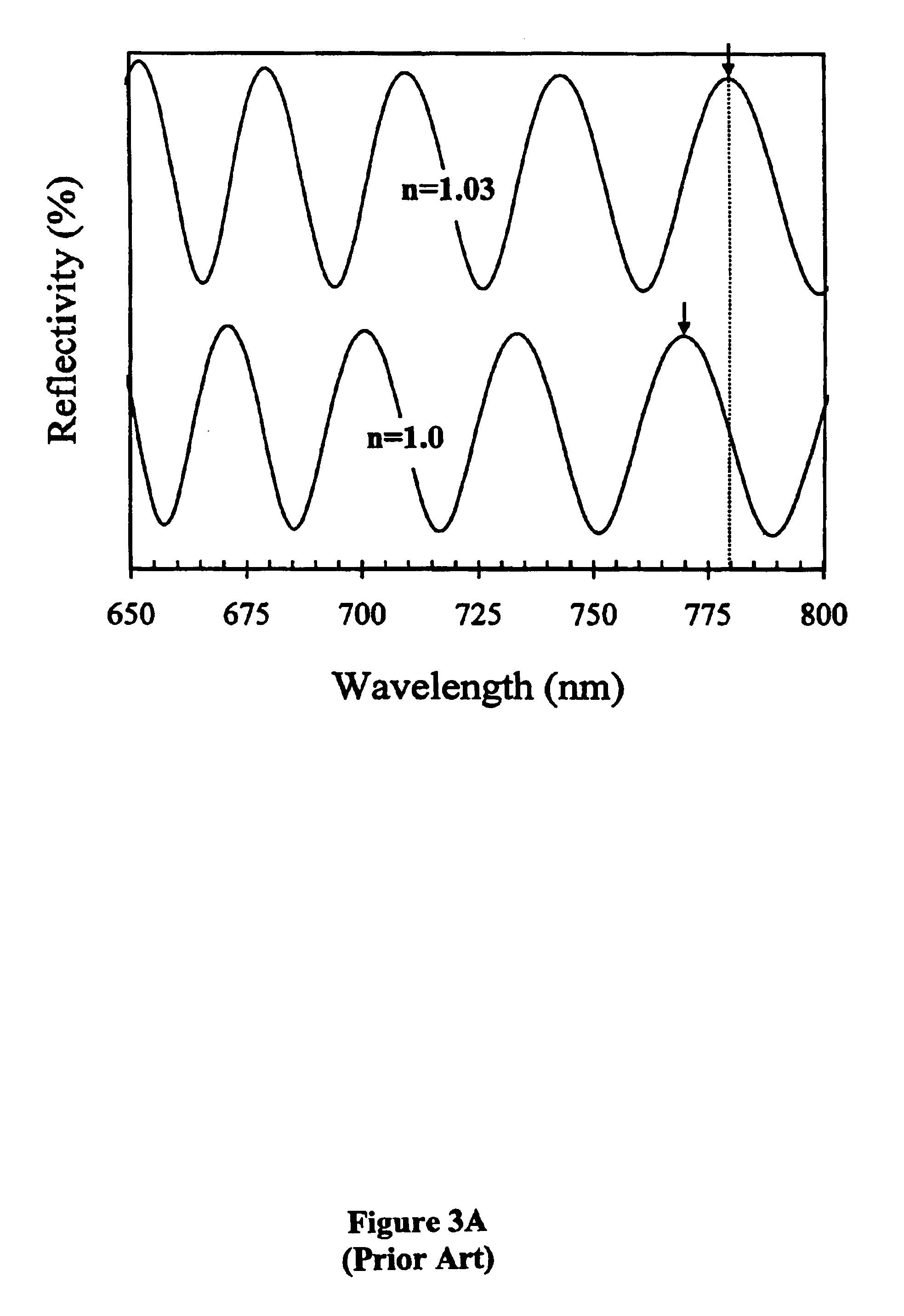
[0083]The effect of DNA—cDNA binding is exemplified in FIG. 4A. By taking the difference between the photoluminescence spectra before and after DNA-cDNA hybridization, a 7 nm red-shift is observed, suggesting that the change in refractive index increased by 0.03. This change is best noted as a change in optical thickness, since a slight increase in thicknes...


PUM

PropertyMeasurementUnit
Pore sizeaaaaaaaaaa
Pore sizeaaaaaaaaaa
Pore sizeaaaaaaaaaa

Abstract

A biological sensor which includes: a porous semiconductor structure comprising a central layer interposed between upper and lower layers, each of the upper and lower layers including strata of alternating porosity; and one or more probes coupled to the porous semiconductor structure, the one or more probes binding to a target molecule, whereby a detectable change occurs in a refractive index of the biological sensor upon binding of the one or more probes to the target molecule. Methods of making the biological sensor and methods of using the same are disclosed, as is a detection device which includes such a biological sensor.

Description

[0001]This application claims the benefit of U.S. Provisional Patent Application Serial No. 60 / 270,527 filed Feb. 21, 2001, which is hereby incorporated by reference in its entirety.[0002]The present invention was made, at least in part, with funding received from the U.S. Army Research Office, grant numbers 5-28888 and 5-27987. The U.S. government may have certain rights in this invention.FIELD OF THE INVENTION[0003]This invention relates to microcavity biosensors which are useful for identifying the presence of a biological target molecule or organism in a sample, as well as methods of making such microcavity biosensors and their use.BACKGROUND OF THE INVENTION[0004]Ever increasing attention is being paid to detection and analysis of low concentrations of analytes in various biologic and organic environments. Qualitative analysis of such analytes is generally limited to the higher concentration levels, whereas quantitative analysis usually requires labeling with a radioisotope or ...

Claims


Application Information

Patent Timeline
IPC IPC(8): C12Q1/68C07H21/04C12M1/00G01N15/06C12M1/34C12M3/00C12Q1/6825G01N21/77G01N33/53G01N33/543G01N33/552G01N33/554G01N33/569G02B6/12H01L51/30
CPCG01N33/54373G01N33/552C12Q1/6825
Inventor CHAN, SELENAFAUCHET, PHILIPPE M.HORNER, SCOTT R.MILLER, BENJAMIN L.
Owner UNIVERSITY OF ROCHESTER
Why Eureka
Try Eureka