Apparatus, method, and program for generating range-image-data
a range image and data technology, applied in the direction of distance measurement, radiation control devices, instruments, etc., can solve the problems of increased pmosfet, increased pmosfet, and difficulty in boosting the output power of a light emitting element such as a light emitting diode or a laser diode employed as a pulsed light source without sacrificing high speed, so as to achieve short distances and reduce the effect of pmosfet and the capacity of photo
- Summary
- Abstract
- Description
- Claims
- Application Information
AI Technical Summary
Benefits of technology
Problems solved by technology
Method used
Image
Examples
first embodiment
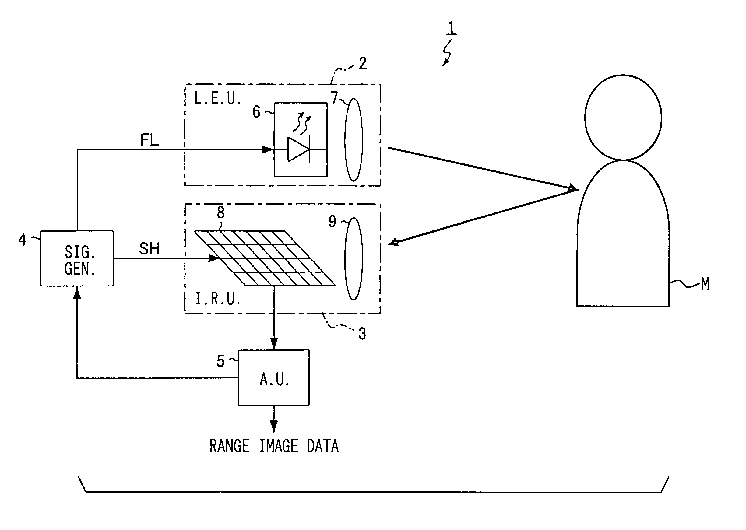
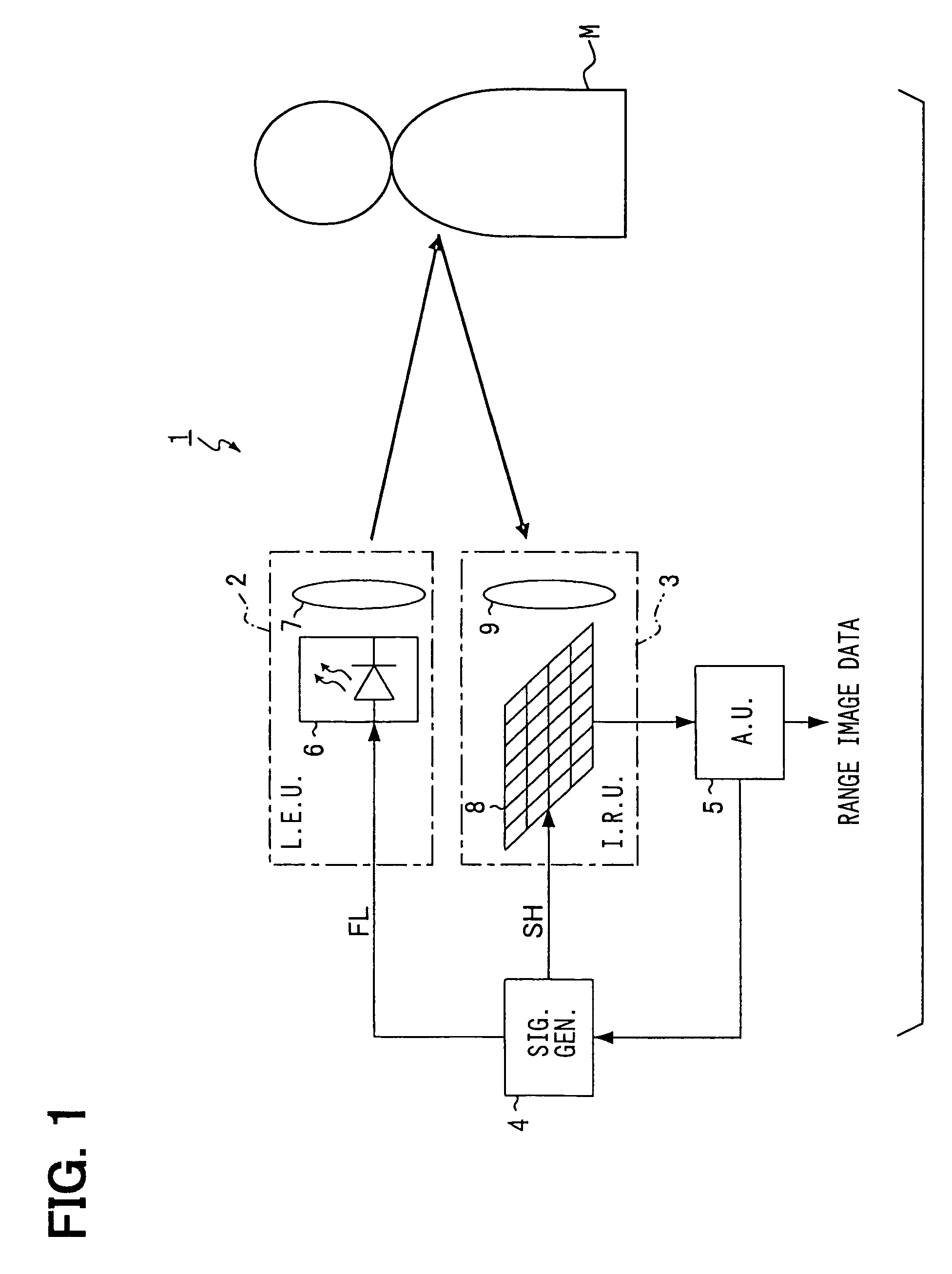
[0068]FIG. 1 is a block diagram showing the whole configuration of a range-image-data-generating apparatus 1 according to a first embodiment. The range-image-data-generating apparatus 1 includes a light emitting unit 2, an image receiving unit 3, a control signal generating unit 4, and an arithmetic unit 5. The light emitting unit 2 emits pulsed light in accordance with an emission signal FL. The image receiving unit 3 receives an image of the objects in a predetermined measuring area in accordance with an exposure signal SH. The control signal generating unit 4 generates emission signal FL and exposure signal SH. The arithmetic unit 5 so controls the control signal generating unit 4 as to generate range-image-data based on the image data from the image receiving unit 3.
[0069]The light emitting unit 2 is either a laser diode (LD) or a light emitting diode (LED), which emits near infrared rays. The light emitting unit 2 includes a light emitting element 6 and a diffusing lens 7. The ...
second embodiment
[0127]A second embodiment of the present invention will be described below.
[0128]This embodiment differs from the first embodiment in operation of the control signal generating unit 4 and a part of the processing executed by the arithmetic unit 5. Therefore, description will be provided below mainly of the operation of the control signal generating unit 4 of this embodiment and the different part of the processing executed by the arithmetic unit 5 of this embodiment.
[0129]Referring to FIG. 9, when the control signal generating unit 4 receives the first command from the arithmetic unit 5, the unit 4 generates an exposure signal SH having a pulse width (exposure time) Tsh1=Tmax×N, where N is an integer larger than one (the first step in FIG. 9). When the control signal generating unit 4 receives the second or third command from the arithmetic unit 5, the unit 4 operates in the same manner as in the first embodiment (the second or third step in FIG. 9). In FIG. 9, Tsh2=Tsh3=Tmax. FIG. ...
third embodiment
[0136]A third embodiment of the present invention will be described below.
[0137]This embodiment differs from the first embodiment in only part of the range-image-data generation. Therefore, mainly the different part will be described.
[0138]The range-image-data generation in this embodiment involves executing Step S160 after repeating Steps S110–S150 m times. The pixel values V4 of reference image data calculated m times at Step S140 are accumulated so that an accumulated value VR4 is obtained. The pixel values V5 of intensity image data calculated m times at Step S150 are accumulated so that an accumulated value VR5 is obtained. Step S160 is to calculate the ratio between the accumulated values VR4 and VR5 so as to find a pixel value VR (VR5 / VR4) of range-image-data.
[0139]The range-image-data-generating apparatus 1 of this embodiment carries out the accumulation while eliminating the noise component V1 due to the background light and the sensor operation. This improves the sensitivi...
PUM
 Abstract
Description
Claims
Application Information
 - R&D
- Intellectual Property
- Life Sciences
- Materials
- Tech Scout
- Unparalleled Data Quality
- Higher Quality Content
- 60% Fewer Hallucinations
Browse by: Latest US Patents, China's latest patents, Technical Efficacy Thesaurus, Application Domain, Technology Topic, Popular Technical Reports.
© 2025 PatSnap. All rights reserved.Legal|Privacy policy|Modern Slavery Act Transparency Statement|Sitemap|About US| Contact US: help@patsnap.com


