Gas agitated multiphase reactor with stationary catalyst solid phase

a multi-phase reactor and catalyst technology, which is applied in the direction of machine/engine, oxygen compound purification/separation, microcapsules, etc., can solve the problems of catalyst attrition, large reaction heat, and uneconomical use, and achieve good heat transfer and thermal control capabilities, the effect of minimizing the attrition of catalys

Active Publication Date: 2007-06-19
PHILLIPS 66 CO
View PDF46 Cites 23 Cited by
  • Summary
  • Abstract
  • Description
  • Claims
  • Application Information

AI Technical Summary

Benefits of technology

[0011]The present catalyst system provides good heat transfer and thermal control capabilities while minimizing catalyst attrition and avoiding the need for liquid / solid separation equipment. The present invention avoids catalyst attrition by containing the solid catalyst particles within containers, which are immersed in the gas-liquid mixture of reactants and products. Also, by containing the catalyst, the removal of the liquid products can be performed without the need for a solid-liquid separation process.

Problems solved by technology

However, most natural gas is situated in areas that are geographically remote from population and industrial centers.
The costs of compression, transportation, and storage make its use economically unattractive.
The reaction gives off a large amount of heat.
When the Fischer-Tropsch reaction is carried out in fixed-bed reactors, this high heat of reaction results in an increase in the temperature of the catalyst bed above that of the surrounding environment.
Excessive temperature rises can lead to inferior product distribution, and can damage the catalyst if not controlled.
This operation is difficult and expensive to implement.
Furthermore, during the separation process, there is a high probability of catalyst attrition, which, in turn, is detrimental to the separation process and may cause loss of catalyst from the reactor and contamination of the products, with negative effects for the processes downstream from the Fischer-Tropsch reactor.

Method used


Image

  • Gas agitated multiphase reactor with stationary catalyst solid phase
  • Gas agitated multiphase reactor with stationary catalyst solid phase
  • Gas agitated multiphase reactor with stationary catalyst solid phase

Examples


second embodiment

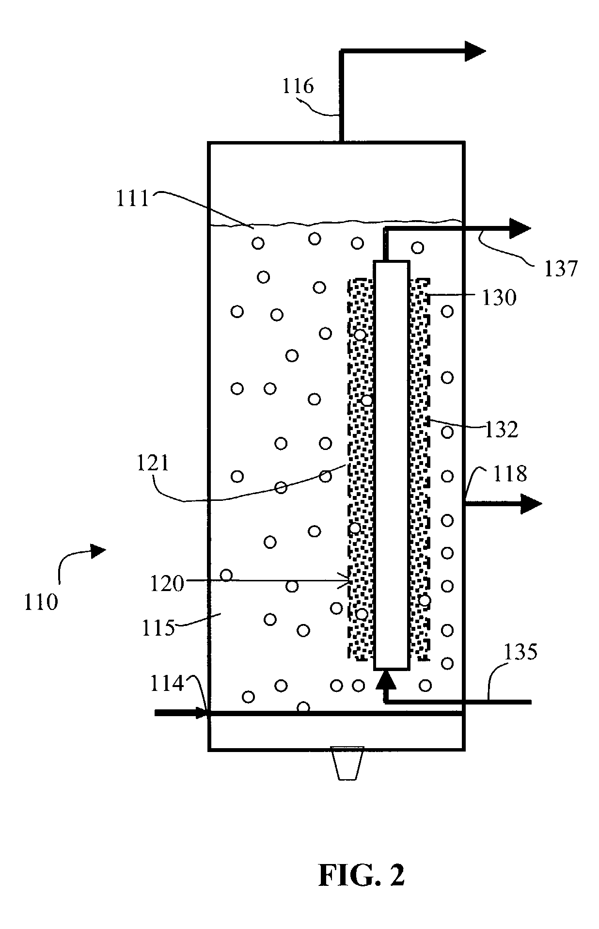
[0030]Referring now to FIG. 2, a second embodiment comprising a reactor 110 includes a catalyst container 120 combined with a cooling system 130. Gas and liquid phase 111 is contained in reaction chamber 115. Cooling system 130 includes a cooling tube 132 having an inlet 135 and an outlet 137. In this embodiment, cooling tube 132 is preferably positioned so that it passes through catalyst container 120. In one preferred embodiment cooling tube 132 and catalyst container 120 are concentric, with catalyst container 120 having a diameter larger than that of cooling tube 132, so that an annulus 121 is defined therebetween. In a preferred embodiment, cooling tube 132 is used to remove heat from reactor 110 by circulating and vaporizing the cooling medium, while annulus 121 contains the catalyst particles. Cooling tube 132 preferably has solid walls, while the catalyst container 120, like catalyst container 20 above, preferably has perforated walls constructed from sintered metal, woven w...

third embodiment

[0031]Referring now to FIG. 3, a third embodiment comprises a reactor 210 including a catalyst container 220 contained within a secondary housing 245. As above, catalyst container 220 is porous and contains the solid catalyst phase, while allowing gas and liquid to pass through. A chamber 247 is defined by each secondary housing 245 and contains gas and liquid phase 211. A second chamber 231 is defined between the outside of secondary housing(s) 245 and the reactor wall. In a preferred embodiment, a cooling medium circulates through chamber 231, forming a cooling system 230. The cooling medium preferably enters reactor 210 at inlet 235 and exits at outlet 237. The cooling medium can fill annulus 231 entirely, or can be further contained in one or more tubes (not shown). The feed gas stream enters chamber 247 via inlet 214 and diffuses into the gas and liquid phase 211. The gas reacts with the catalyst in catalyst container 220 to form hydrocarbons. Liquid products are withdrawn at o...

fourth embodiment

[0034]Referring now to FIG. 5, a fourth embodiment comprises a reactor 310 including a catalyst container 320 combined with a cooling system 330. As in FIG. 1, the cooling medium enters reactor 310 via inlet 335 and exits via outlet 337 and a reaction chamber 315 is defined between the outside of catalyst container 320 and the wall of reactor housing 312. As above, the gas and liquid phases occupy chamber 315. Unlike the embodiment shown in FIG. 1, a collection chamber 347 is defined directly above chamber 315 and catalyst container 320 and contains a portion of the gas and liquid phases. It should be noted that collection chamber 347 is separated from chamber 315 by a divider 327, such that fluid communication between chamber 315 and collection chamber 347 can occur only through the upper end 328 of catalyst container 320. In this embodiment, a primarily liquid stream leaves the reactor via liquid outlet 317, which is preferably positioned so as to remove liquid from collection cha...


PUM

PropertyMeasurementUnit
temperaturesaaaaaaaaaa
molar ratioaaaaaaaaaa

Abstract

An apparatus for converting a gaseous and/or liquid feed fluid to gaseous and/or liquid products using a solid catalyst comprises a reactor, a liquid phase disposed within the reactor volume, a fixed catalyst at least partially disposed in the liquid phase, a cooling system having a cooling element in thermal contact with the liquid phase, a feed inlet positioned to feed the feed fluid into the reactor volume, and a fluid outlet in fluid communication with the liquid phase. The catalyst is contained in a catalyst container and the container may be adjacent to said cooling element, extend through said cooling element, or may surround the catalyst container. The catalyst may be a Fischer-Tropsch catalyst.

Description

RELATED APPLICATIONS[0001]NoneSTATEMENT REGARDING FEDERALLY SPONSORED RESEARCH OR DEVELOPMENT[0002]Not applicableTECHNICAL FIELD OF THE INVENTION[0003]The present invention relates to a method and apparatus for converting synthesis gas, i.e., a mixture of carbon monoxide and hydrogen, to hydrocarbons, typically referred to as the Fischer-Tropsch reactions or the Fischer-Tropsch process. More particularly this invention relates to the use of a gas agitated multiphase reactor to achieve both reaction of the syngas and separation of the hydrocarbon product.BACKGROUND[0004]Large quantities of methane, the main component of natural gas, are available in many areas of the world, and natural gas is predicted to outlast oil reserves by a significant margin. However, most natural gas is situated in areas that are geographically remote from population and industrial centers. The costs of compression, transportation, and storage make its use economically unattractive. To improve the economics...

Claims


Application Information

Patent Timeline
Patent Type & Authority Patents(United States)
IPC IPC(8): C07C27/26B01J8/04B01J10/00C07C27/22C10G2/00
CPCB01J8/0292B01J8/067B01J10/007C07C27/22C10G2/341B01J2208/00132B01J2208/00194B01J2208/00203B01J2208/00814B01J2208/00884B01J2219/00081
Inventor MOHEDAS, SERGIO R.ESPINOZA, RAFAEL L.ZHANG, JIANPING
Owner PHILLIPS 66 CO
Why Eureka
Try Eureka