
Microstrip phase shifter

a phase shifter and microstrip technology, applied in waveguides, antenna details, antennas, etc., can solve the problems of affecting the quality of the signal, and requiring a lot of sliding contact, so as to minimize the cost of both materials and assembly, and the effect of simple construction

Inactive Publication Date: 2007-06-19
ANDREW LLC
View PDF83 Cites 29 Cited by
  • Summary
  • Abstract
  • Description
  • Claims
  • Application Information

AI Technical Summary

Benefits of technology

[0012]The phase shifter employs capacitive coupling between moving parts. The capacitive coupling between the moving parts can be maintained by providing a dielectric spacer between the coupling arm and feed lines disposed on the planar surface. The phase shifter can further comprise a spring assembly for uniformly applying a distributed pressure to the coupling arm to help maintain the aforementioned capacitive coupling. The spring assembly can be implemented as a thin and wide cylindrical structure that applies force over a large area of the coupling arm.
[0013]The phase shifter can also include support traces that are positioned on the arm as well as on a planar support structure that includes the feed lines that engage with the coupling ring and wiper element. The support traces can help facilitate smooth rotation of the phase shifter by providing opposing forces relative to the forces generated as the wiper element of the coupling arm moves over an output feed line.
[0014]The phase shifter can include a key cooperatively engaged to a shaft for transferring movement of the shaft to the coupling arm. The key can also provide rigid support to the coupling arm. A bearing-seal, which engages and circumscribes the shaft and is located in a hole in the tray, can facilitate smooth rotation of the phase shifter by providing a bearing surface for the outer diameter of the shaft. Further, the bearing-seal provides a moisture barrier and protects against the elements.
[0015]The materials of the present invention lend themselves to efficient and cost effective manufacturing of the phase shifter. The coupling ring, wiper element and the mid portion connecting the coupling ring to the wiper element of the coupling arm can be made from microstrip materials, such as copper, that can be formed during etching-type manufacturing processes. The coupling arm can further comprise a printed circuit board material.
[0018]The structure and method of the invention can provide a phase shifter that has low PIM, low return losses, supports large RF bandwidths and provides a highly reliable way to adjust phases in RF signals that is durable and repeatable over an extended life cycle.
[0022]The phase shifter of the invention is of a simple construction, designed to minimize cost of both materials and assembly.

Problems solved by technology

Various types of phase shifters have been designed for particular uses, but while useful in particular environments, the disadvantages of many phase shifter designs have limited their use in the field of multi-carrier, high power antennas, such as base station antennas as used in the mobile communications industry.
This technique usually requires rather complex sliding-contacts and can be very sensitive to corrosion.
A drawback of this type phase shifter that employs moveable or sliding contacts is that it is susceptible to generating adverse Passive Intermodulation (PIM) that occurs especially when high power and multi-carrier electromagnetic energy is directed over metal contacts.
However, these solid state electronic phase shifting methods are usually not compatible with high power levels due to their inherent nonlinearities, and active solid state solutions require power amplifiers which can be very large and expensive.
However, ferrite phase shifters can be very large, heavy, and expensive.
While recently developed thin-film techniques have reduced their size to some extent, such ferrite phase shifters are usually nonlinear at high power levels making them inappropriate for multi-carrier communications operating at high power levels.
Other conventional phase shifting techniques use a mechanical movement of a dielectric material into electrical field lines, but the effective relative phase shift generated can be small for materials with low dielectric constants and hence require large-sized phase shifters for practical applications.
For high-dielectric constant materials, a significant impedance mismatch can occur at the interface to the dielectric loaded region, which causes an undesirable return loss.
Further, solutions with high dielectric materials are further prone to power loss into dielectric resonant modes.
The competing mechanical and electrical demands for phase shifters, especially in constrained environments of many communications systems, makes most of these conventional designs inappropriate to meet the cost, size and performance requirements of certain systems, especially communication system antennas characterized by high power and multi-carrier use.

Method used


Image

  • Microstrip phase shifter
  • Microstrip phase shifter
  • Microstrip phase shifter

Examples


Embodiment Construction

[0047]A phase shifter can comprise a coupling arm, a key, a spring, and a support architecture that fastens the phase shifter to a substantially planar surface while permitting rotation of certain components of the phase shifter relative to the planar surface. The support architecture can be rotated manually or with a machine such as a motor. The coupling arm can comprise a coupling ring, a wiper element, a support trace, and a dielectric spacer.

[0048]Referring now to the drawings, in which like numerals represent like elements throughout the several figures, aspects of the present invention and the illustrative operating environment will be described.

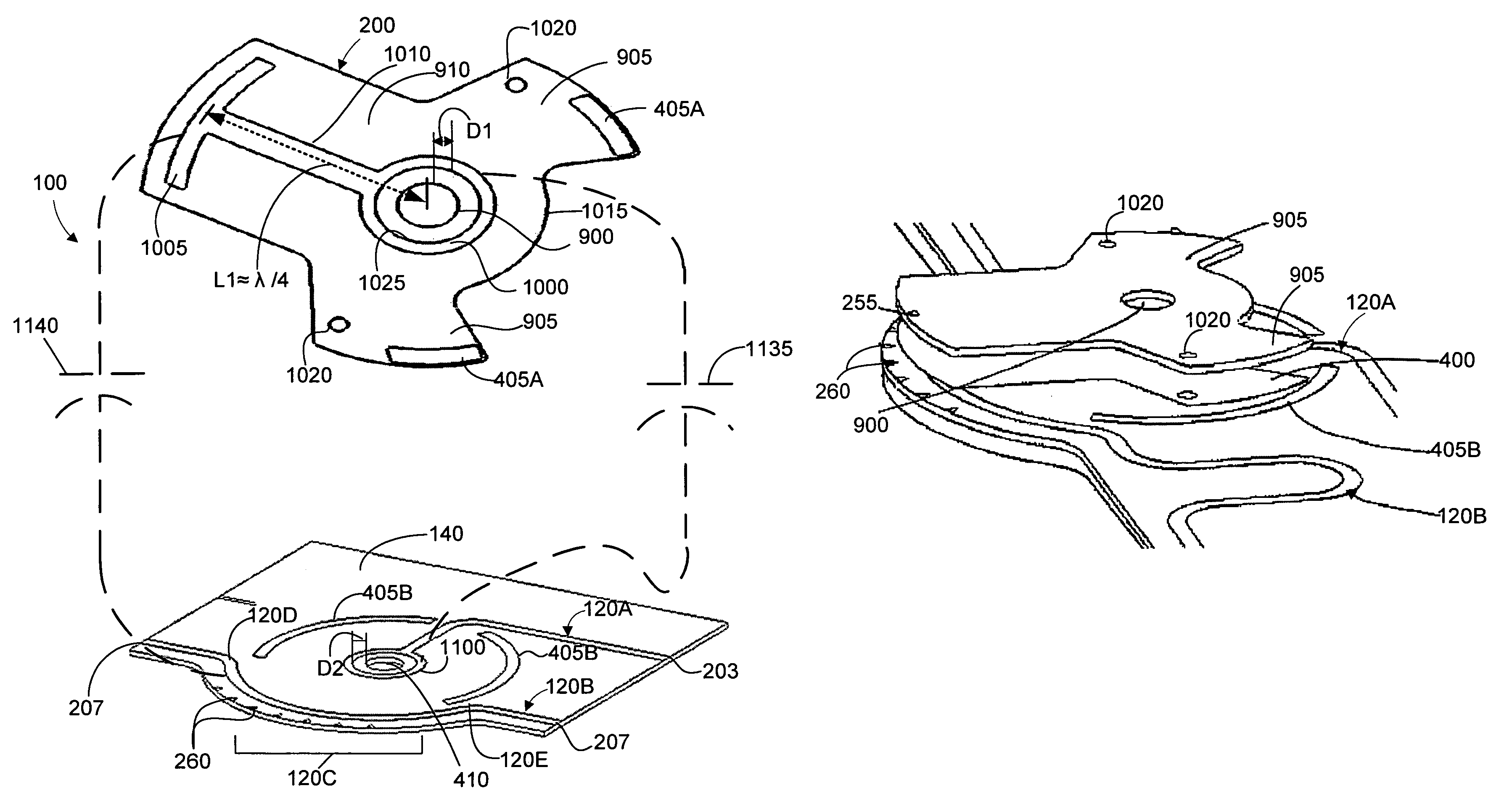
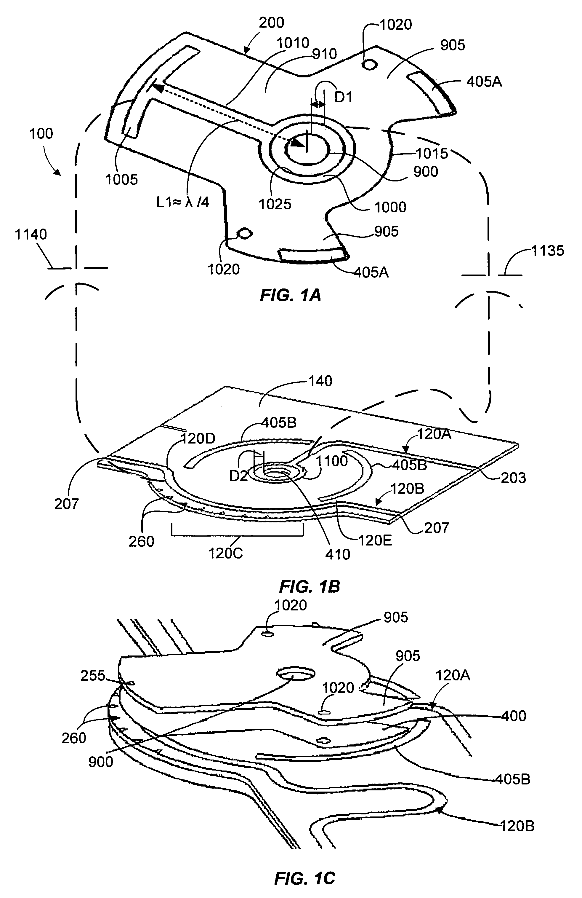
[0049]Referring now to FIG. 1A, this figure illustrates a bottom view of a coupling arm 200 according to one exemplary embodiment of the present invention. The side illustrated in FIG. 1A will face the side illustrated in FIG. 1B when the coupling arm 200 is rotatably fastened to a planar surface 140 illustrated in FIG. 1B.

[0050]The co...


PUM


Abstract

A phase shifter adjusts the phase between two segments of an RF feed line that are fed with the phase shifter. Specifically, the phase shifter adjusts the phase between two signals in RF feed line segments by changing the electrical path lengths that RF energy travels down in each respective RF feed line. The phase shifter includes a coupling arm, a key, a spring, and a support architecture that fastens the phase shifter to a substantially planar surface. The support architecture is rotated manually or with a machine such as a motor. The coupling arm can include a coupling ring, a wiper element, a support trace, and a dielectric spacer. The phase shifting system is a relatively compact structure having a predetermined value of capacitance maintained between a coupling ring disposed on the coupling arm and a coupling ring disposed on a planar surface.

Description

STATEMENT REGARDING RELATED APPLICATIONS[0001]The present application claims priority to U.S. Provisional Application entitled “Microstrip Phase Shifter,” filed on Aug. 23, 2001 and assigned U.S. application Ser. No. 60 / 314,507. The entire contents of the provisional application are hereby incorporated by reference.FIELD OF INVENTION[0002]The present invention relates to adjusting electrical phase of signals, and more specifically, to the phase adjustment of electrical signals as used in RF feed lines in wireless communication products, such as in antennas.BACKGROUND OF THE INVENTION[0003]Phase shifters are known for adjusting the phase of electrical signals in various kinds of products and systems. Phase shifters are especially useful in navigation, tracking and communication equipment to control characteristics of the associated electrical signals. Various types of phase shifters have been designed for particular uses, but while useful in particular environments, the disadvantages...

Claims


Application Information

Patent Timeline
IPC IPC(8): H01P3/08H01P1/18H01Q1/24H01Q1/38H01Q3/26H01Q21/08
CPCH01P1/184H01Q1/246H01Q1/38H01Q3/26H01Q21/08
Inventor PHILLIPS, SARAALABURDA, JACOBDAWSON, DOUGLAS E.
Owner ANDREW LLC
Learn More