Computed tomographic scanner using rastered x-ray tubes

a computed tomographic and x-ray tube technology, applied in the direction of material analysis using wave/particle radiation, instruments, nuclear engineering, etc., can solve the problems of unacceptably long time required to scan objects, slow scanning speed for some applications, and multiplying the number of detectors that are used, so as to reduce the x-ray power required for each tube and reduce the cooling requirement of the anode

Active Publication Date: 2007-06-19
MORPHO DETECTION INC
View PDF5 Cites 148 Cited by
  • Summary
  • Abstract
  • Description
  • Claims
  • Application Information

AI Technical Summary

Benefits of technology

[0021]In another embodiment, the scanner utilizes two or more subscan assemblies, each with its own set of detectors. The scan assemblies are offset in the depth direction allowing scanning of all the assemblies simultaneously. Simultaneous scanning of multiple planes provides several advantages. The x-ray flux increases proportionally to the number of tubes scanning simultaneously. The scanning speed increases because the time required to traverse the entire source path is divided by the number of assemblies. Alternatively, the x-ray power required for each tube can be reduced while maintaining the same flux and scan speed, reducing the cooling required for the anodes.

Problems solved by technology

One drawback to conventional CT systems is their slow scanning speed for some applications.
As a result, if views cannot be generated quickly enough, the time required to scan an object will be unacceptably long.
However, the gantry can be large and rotating it at high speeds can introduce its own problems, not the least of which is the increased centrifugal force exerted on the gantry.
However, this requires multiplying the number of detectors that are used.
This adds cost and complexity to the system.
This assembly also makes it difficult to scan objects on a conveyor belt because the tube assembly occupies a large volume on one end of the scanner.
The long propagation paths also result in a large overall size for the equipment and increased sensitivity to electromagnetic noise, making it inappropriate for use in industrial environments such as airports.
The large assembly, which must be kept under vacuum, is also difficult to make leak proof.
The Boyd design also has the drawback that the arc of the x-ray source overlaps the arc of the detectors (i.e., source arc+detector arc is greater than 360 degrees), which means that the detector arc and source arc must be displaced in the depth direction.
The cone angle, if uncorrected, leads to inaccurate image reconstruction.
However, for many applications, conventional x-ray tubes cannot be spaced close enough to one another to meet the application's resolution requirements.
However, this technology does not appear to be advanced enough for commercial application at this time at voltages greater than 60 kV, which makes this approach inappropriate for medical, baggage scanning and many industrial applications that may require significantly greater x-ray energies.
This approach also requires complex systems to distribute power and cooling to the large number of x-ray tubes.

Method used


Image

  • Computed tomographic scanner using rastered x-ray tubes
  • Computed tomographic scanner using rastered x-ray tubes
  • Computed tomographic scanner using rastered x-ray tubes

Examples


Embodiment Construction

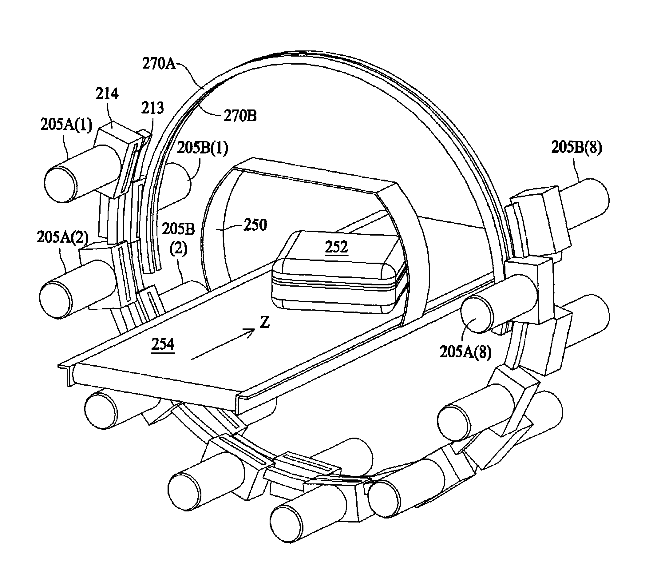
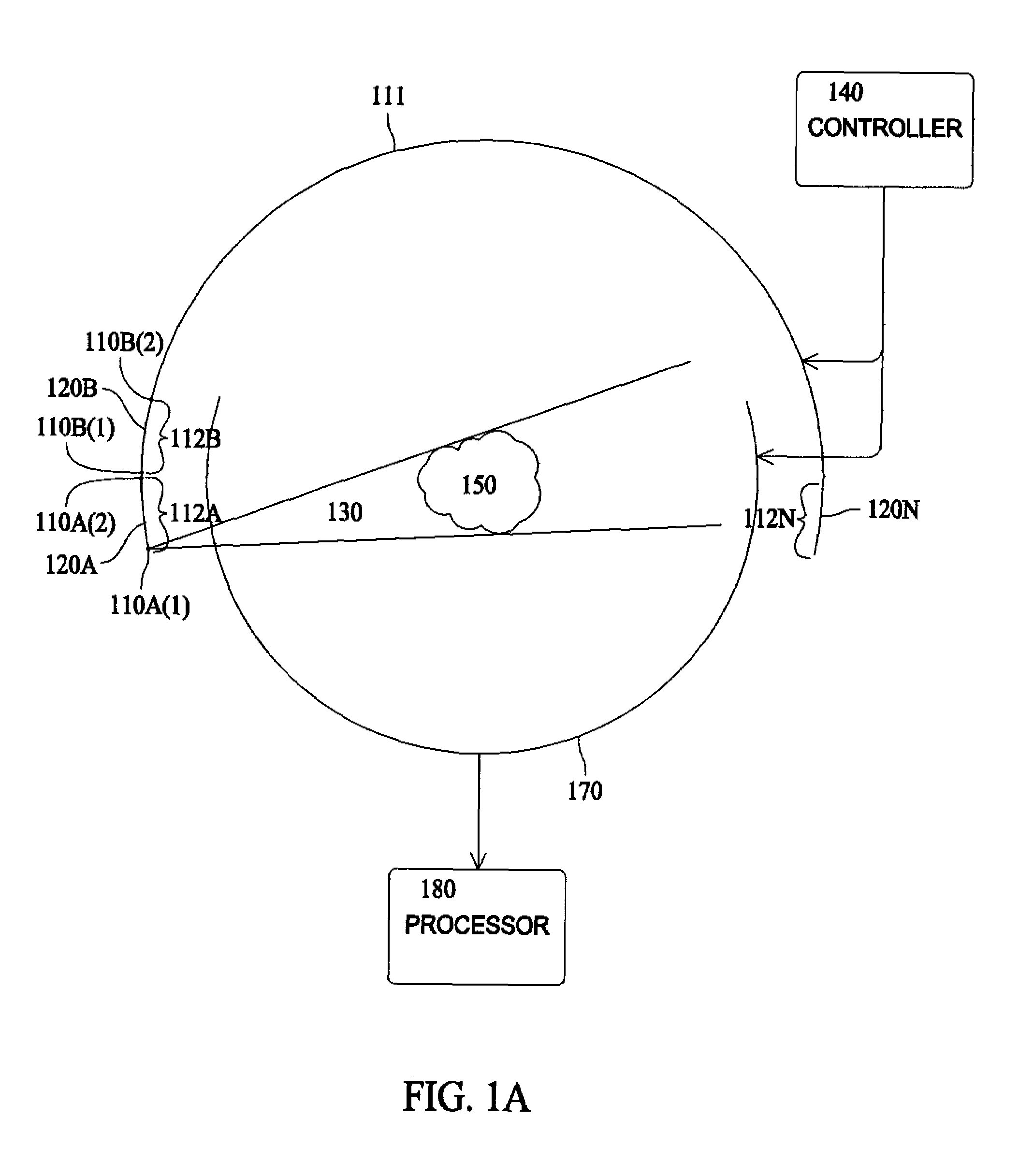
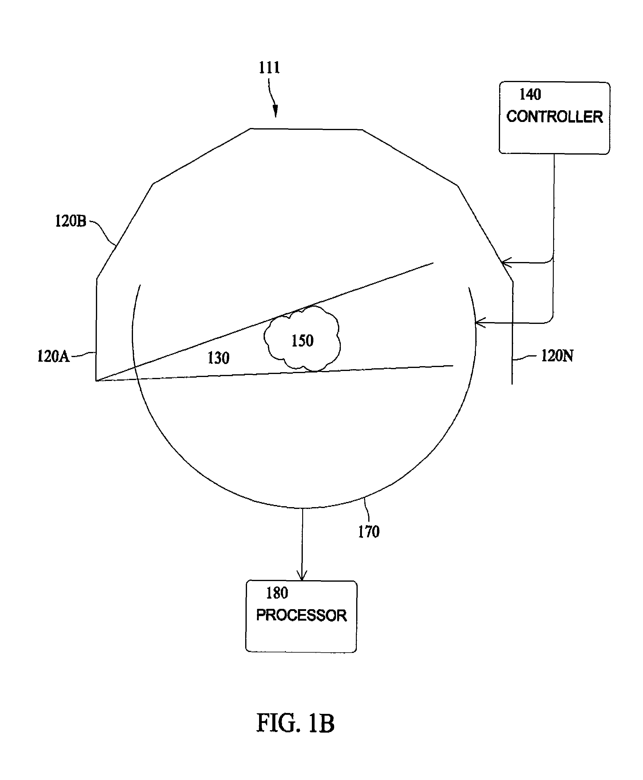
[0034]FIGS. 1A–1D are simplified schematic diagrams illustrating CT scanners according to the present invention. In these diagrams, the CT scanner is designed to scan object 150. In many applications, the CT scanner is designed to scan a certain volume or cross-sectional area 150 and objects to be scanned are placed in or moved through the target area 150. For purposes of this application, the terms object and target area or target volume will be used interchangeably. The line 111 represents the source path for the CT scanner and points along the source path shall be referred to as source points. X-ray fans 130 are projected from source points through the object 150 to the detector array 170.

[0035]Generally speaking, the CT scanner is designed so that each point in the object 150 is interrogated by x-ray beams propagating at different angles (typically rays spanning 180 degrees are sufficient). A controller 140 controls the source path 111 and / or detector array 170. For example, the...


PUM

PropertyMeasurementUnit
voltagesaaaaaaaaaa
anglesaaaaaaaaaa
speedaaaaaaaaaa

Abstract

A high speed computed tomography x-ray scanner using a plurality of x-ray generators. Each x-ray generator is scanned along a source path that is a segment of the scanner's source path such that each point in the source path is scanned by at least one tube. X-ray generators and detectors can be arranged in different scan planes depending on the available hardware so that a complete and near planar scan of a moving object can be assembled and reconstructed into an image of the object.

Description

BACKGROUND OF THE INVENTION[0001]1. Field of the Invention[0002]This invention relates generally to computed tomographic (CT) scanners and, more particularly, to CT scanners that use electron rastered x-ray generators or other means of projecting an electron beam to different positions on the anode.[0003]2. Description of the Related Art[0004]For many applications, CT is currently a preferred method for scanning objects using x-rays. CT allows a two- or three-dimensional image of the interior of an object to be constructed without physical intrusion into the object. For example, CT can be used to develop a three-dimensional image of the contents of baggage without physically opening the baggage, as would be useful in airport security screening. CT scanners are also used for medical applications (for example to scan different parts of the body), in industrial applications (for example in rapid prototyping and reverse engineering), and for non-destructive testing (for example to detec...

Claims


Application Information

Patent Timeline
Patent Type & Authority Patents(United States)
IPC IPC(8): G01N23/04
CPCG01N23/046G01N2223/419A61B6/027
Inventor BENDAHAN, JOSEPHGARMS, WALTER I
Owner MORPHO DETECTION INC
Why Eureka
Try Eureka