Electrode for rechargeable lithium battery and rechargeable lithium battery

a rechargeable lithium battery and lithium battery technology, applied in secondary cell servicing/maintenance, cell components, sustainable manufacturing/processing, etc., can solve the problem of large strain produced in the current collector and achieve the effect of improving the charge-discharge cycle characteristics and high charge-discharge capacity

Inactive Publication Date: 2007-07-10
SANYO ELECTRIC CO LTD
View PDF69 Cites 91 Cited by
  • Summary
  • Abstract
  • Description
  • Claims
  • Application Information

AI Technical Summary

Benefits of technology

[0005]The inventors of this application have found that an electrode including a thin film composed of active material capable of lithium storage and release, such as a microcrystalline or amorphous silicon thin film, deposited on a current collector such as a copper foil can prevent the active material from separating or falling off therefrom during a charge-discharge reaction and, when incorporated in a rechargeable lithium battery, can exhibit a high charge-discharge capacity and improved charge-discharge cycle characteristics.

Problems solved by technology

However, a large strain is occasionally produced in the current collector as a result of a charge-discharge reaction of such a rechargeable lithium battery.

Method used


Image

  • Electrode for rechargeable lithium battery and rechargeable lithium battery
  • Electrode for rechargeable lithium battery and rechargeable lithium battery
  • Electrode for rechargeable lithium battery and rechargeable lithium battery

Examples


example 1

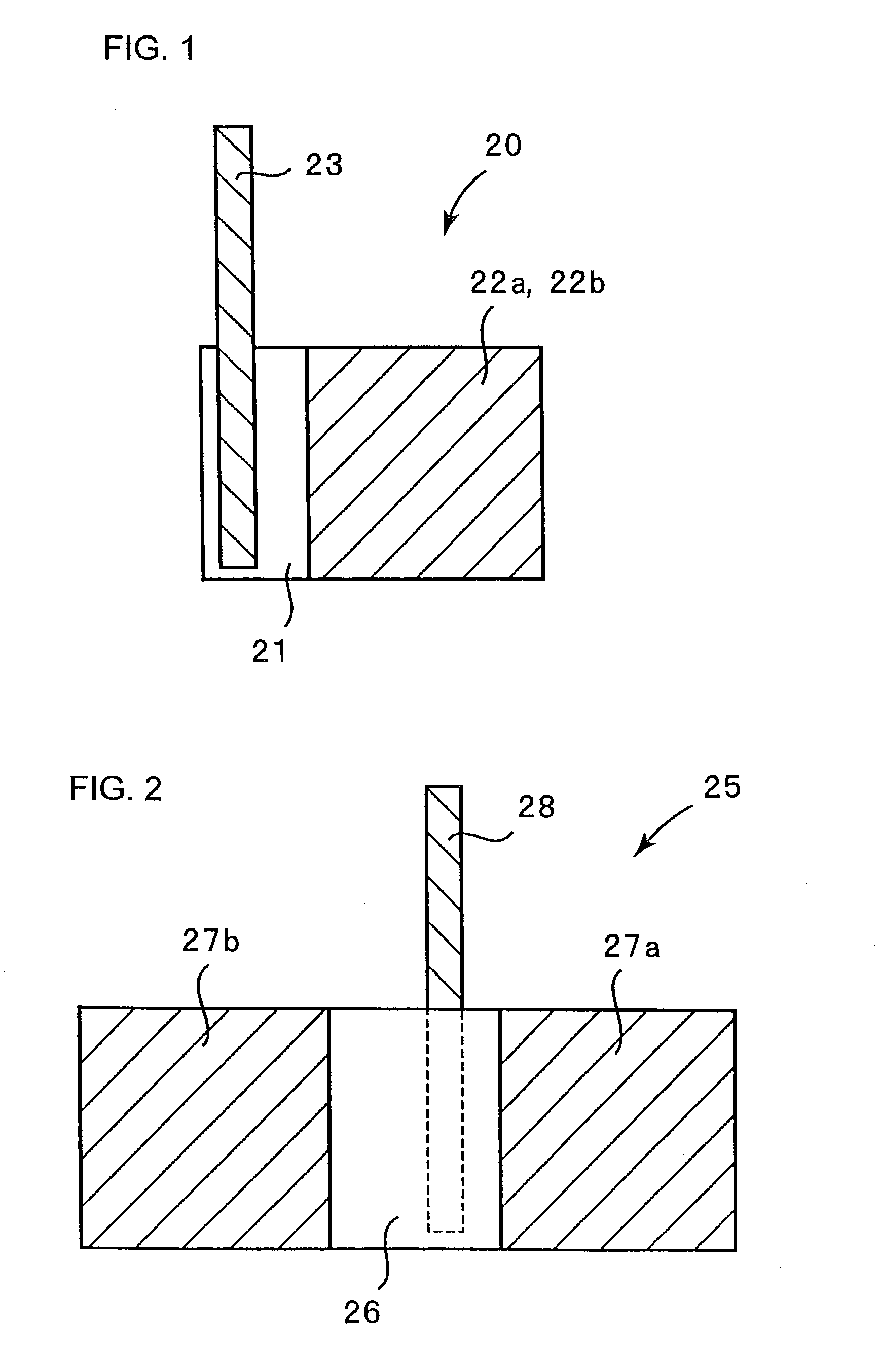
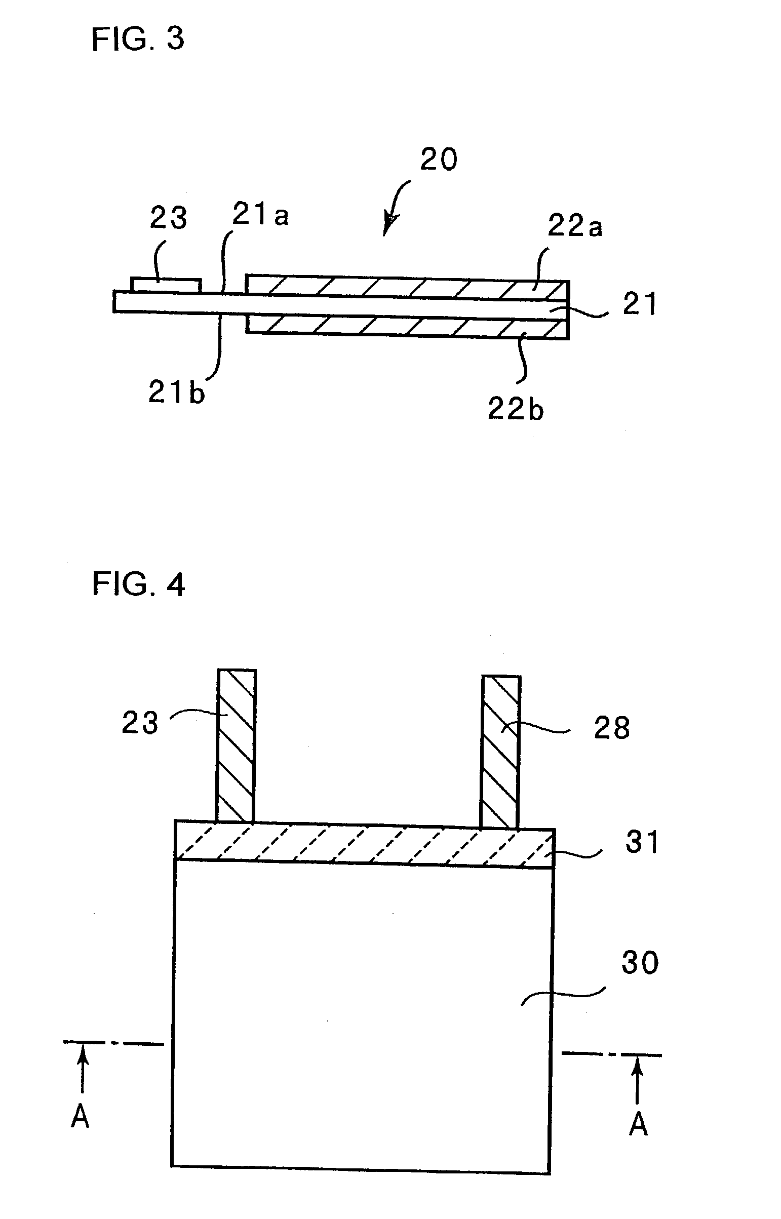
[0113](Fabrication of Negative Electrode)

[0114]A negative electrode 20 shown in FIGS. 1 and 3 was fabricated. FIGS. 1 and 3 are a plan view and a side view, respectively. As shown in FIG. 3, an electrolytic copper foil 21 carries a microcrystalline silicon thin film 22a on its one face 21a and a microcrystalline silicon thin film 22b on its other face 21b.

[0115]The electrolytic copper foil 21 was prepared by immersing a rolled copper foil in an electrolyte solution and then effecting copper deposition on its opposite faces by an electrolytic process so that the copper foil was roughened at its opposite faces. The electrolytic copper foil 21 is 20 mm×30 mm in size and carries the micro-crystalline silicon thin film 22a or 22b on a 20 mm×20 mm region of each face thereof. The electrolytic copper foil 21 is 18 μm thick and the microcrystalline silicon thin films 22a and 22b were both about 5 μm thick. Each surface 21a or 21b of the electrolytic copper foil 21 has a surface roughness R...

example 2

[0138]In the construction of a rechargeable lithium battery in accordance with the present invention, the positive and negative electrodes were combined into a stacked structure shown in FIG. 6.

[0139](Fabrication of Negative Electrode)

[0140]The electrolytic copper foil of Example 1 was used having opposite rough surfaces. An about 5 μm thick, microcrystalline silicon thin film was formed on each face of the electrolytic copper foil in the same manner as in Example 1 to fabricate a negative electrode.

[0141](Fabrication of Positive Electrode)

[0142]85 parts by weight of LiCoO2 powder obtained in the same manner as in Example 1, 10 parts by weight of artificial graphite powder as an electroconductive material, and a 5 wt. % N-methylpyrrolidone aqueous solution containing 5 parts by weight of polytetrafluoroethylene as a binder were mixed to provide a mix slurry for positive electrode. This slurry was applied onto both sides of a 20 μm thick aluminum foil and then dried. As a result, a p...

example 3

[0152]A coin-type rechargeable lithium battery shown in FIG. 8 was constructed. The microcrystalline silicon thin films 52a and 52b are provided on opposite faces of the current collector 51 to constitute a negative electrode. The negative current collector 51 is the electrolytic copper foil roughened at its both surfaces, which was used in Example 2. Those microcrystalline silicon thin films 52a and 52b were formed in the same manner as in Example 2.

[0153]The layers 55a and 55b of positive active material are provided on inner faces of the U-folded positive current collector 54 to constitute a positive electrode. Used for the positive current collector 54 is an aluminum foil which is similar in type to that used in Example 2. The layers 55a and 55b of positive active material are formed in the same manner as in Example 2.

[0154]As shown in FIG. 8, the positive current collector 54 is folded in a U-shape to define an inner space into which the negative electrode is inserted. A separa...


PUM

PropertyMeasurementUnit
surface roughness Raaaaaaaaaaa
surface roughnessaaaaaaaaaa

Abstract

An electrode for a rechargeable lithium battery characterized in that thin films of active material capable of lithium storage and release, i.e., microcrystalline or amorphous silicone thin films are deposited on opposite faces of a plate-form current collector.

Description

TECHNICAL FIELD[0001]The present invention relates to a novel electrode for a rechargeable lithium battery and also to a rechargeable lithium battery using the same.BACKGROUND ART[0002]The battery performance of rechargeable lithium batteries recently under intensive research and development, such as charge-discharge voltage, cycle life characteristics or storage characteristics, depends largely upon the types of the electrodes used. This has led to the attempts to better battery performance by improving electrode active materials.[0003]The use of metallic lithium for the negative active material, although possible to construct a battery with high energy density per weight and volume, presents a problem that the lithium deposited on charge grows into dendrite which could cause internal short-circuiting.[0004]Rechargeable lithium batteries are reported (Solid State Ionics, 113–115, p 57 (1998)) which use an electrode consisting of aluminum, silicon, tin or the like that is electroche...

Claims


Application Information

Patent Timeline
Patent Type & Authority Patents(United States)
IPC IPC(8): H01M4/70H01M4/36H01M4/13H01M4/134H01M4/139H01M4/1395H01M4/38H01M4/40H01M4/66H01M6/10H01M6/40H01M10/05H01M10/052H01M10/0583H01M10/0585H01M10/0587H01M10/42H01M10/44H01M50/103
CPCH01M4/134H01M4/366H01M4/40H01M4/661H01M4/667H01M10/052H01M2/0207H01M4/04H01M4/131H01M4/1395H01M4/38H01M4/405H01M4/485H01M4/525H01M4/58H01M4/70H01M6/40H01M10/0587H01M10/44H01M2010/4292Y02E60/122H01M4/386Y02E60/10Y02P70/50H01M50/103H01M4/66
Inventor IKEDA, HIROAKIFUJIMOTO, MASAHISAFUJITANI, SHINASAOKA, KENJIMATSUTA, SHIGEKIDOMOTO, YOICHIOHSHITA, RYUJISHIMA, MASAKIYAGI, HIROMASATARUI, HISAKIKUROKAWA, HIROSHIKATO, YOSHIONAKAJIMAYOSHIDA, TOSHIKAZU
Owner SANYO ELECTRIC CO LTD
Why Eureka
Try Eureka