Fluorescence detector geometry

a detector geometry and fluorescence technology, applied in the field of fluorescence detectors, can solve the problems of reducing the size of the sample, short cell pathway, and comparatively low output signal magnitude, and achieve the effects of increasing the path-length of the excitation beam, increasing the detection sensitivity, and increasing light absorption

Inactive Publication Date: 2007-07-31
WATERS TECH CORP
View PDF26 Cites 5 Cited by
  • Summary
  • Abstract
  • Description
  • Claims
  • Application Information

AI Technical Summary

Benefits of technology

[0011]The photometric flow cell according to the invention provides more light absorption by the sample due to an increased path-length of the excitation beam. Increased excitation path-length allows a sample to produce more fluorescent photons causing the fluorescence detector to have greater detection sensitivity. As a consequence of the flow cell design, the path length traversed by the emitted photons is small, avoiding non-linearity associated with self absorption.
[0012]According to the invention, a photometric apparatus for small sample volumes is comprised of a cell body. The cell body has light input optics arranged adjacent to the surface of the cell body. A light source is presented, generally a high-radiance portion of a high-pressure Xenon arc, and a monochromator selects light of a predetermined wavelength or wavelength range through the light input optics. The light input optics are comprised of very low aberration optics, so that the small, high-radiance portion of the high-pressure Xe arc is focused, after wavelength selection, onto the small end cross-section of the flow cell, thus providing axial illumination of the flow channel with increased path-length.
[0013]The axial illumination of the flow cell causes the sample to produce greater fluorescence that is emitted in all directions. More fluorescence is collected from the long side of the flow cell by the placement of a mirror surface opposite the emission window that directs errant fluorescent emission through the emission window. Additional sensitivity is achieved within the inventive flow cell by the retro-reflection of the excitation beam off the curved end mirror surface to cause the beam to double-pass the flow channel, thereby significantly increasing the path-length. Minimum volume at this extended path-length is accomplished by utilizing the referenced low aberration optics designed for the source collection and excitation monochromator, so that the small, high-radiance portion of the high-pressure Xenon arc is focused axially onto the small end cross-section of the flow cell. The axial illumination of the flow cell is achieved by having the plane of the excitation optics horizontal, resulting in the long axis of the flow cell being horizontal and the plane of the emission optics being vertical.
[0014]This change in the geometry of the optics on two separate planes allows for improved sensitivity in photo-detection by allowing an increased path-length by the axial illumination of the flow cell and the collection of the resulting emission from the long slit-shaped side of the flow cell, parallel to the axis of the flow cell.
[0015]Advantages of the present invention include the significantly increased path-length through the flow cell resulting in greater intensity of the output signal. This advantage allows greater sensitivity for small samples compared with conventional sized flow cells. A further benefit of the present invention is the simplicity of measuring the signal because of the lack of pre-filter and post-filter effects of solvents.

Problems solved by technology

Standard detection flow cells used in conventional liquid chromatography instruments have the disadvantage that their cell pathways, as a function of their design, are unfortunately short.
One of the more significant problems is the comparatively low magnitude of the output signal due to the limits encountered by the relatively short path-length.
Unfortunately, this conventional method of fluorescent sample detection is degraded as the size of the sample is reduced.
However, in spite of their apparent demonstrated advantages, they currently receive little use because silica-based glasses have high refractive indices (n>1.46).
The requirement for total internal reflection dictates that the refractive index of the core sample liquid exceed that of the capillary wall, which severely limits utility.
Hollow glass or silica waveguides used with low-refractive index liquids have drawbacks from an optical point of view.
From a spectroscopic point of view, propagation in the glass wall has several adverse consequences.
Also, particularly in Raman studies, propagation in the glass wall results in the generation of silica bands, contributing to unwanted background noise.
However, the emitted fluorescence must travel the length of the light guiding section of the sample liquid and may be subject to re-absorption unless the solutions are extremely dilute.
Self absorption can severely limit the linear dynamic range of sample concentration in a light guiding cell.

Method used


Image

  • Fluorescence detector geometry
  • Fluorescence detector geometry
  • Fluorescence detector geometry

Examples


Embodiment Construction

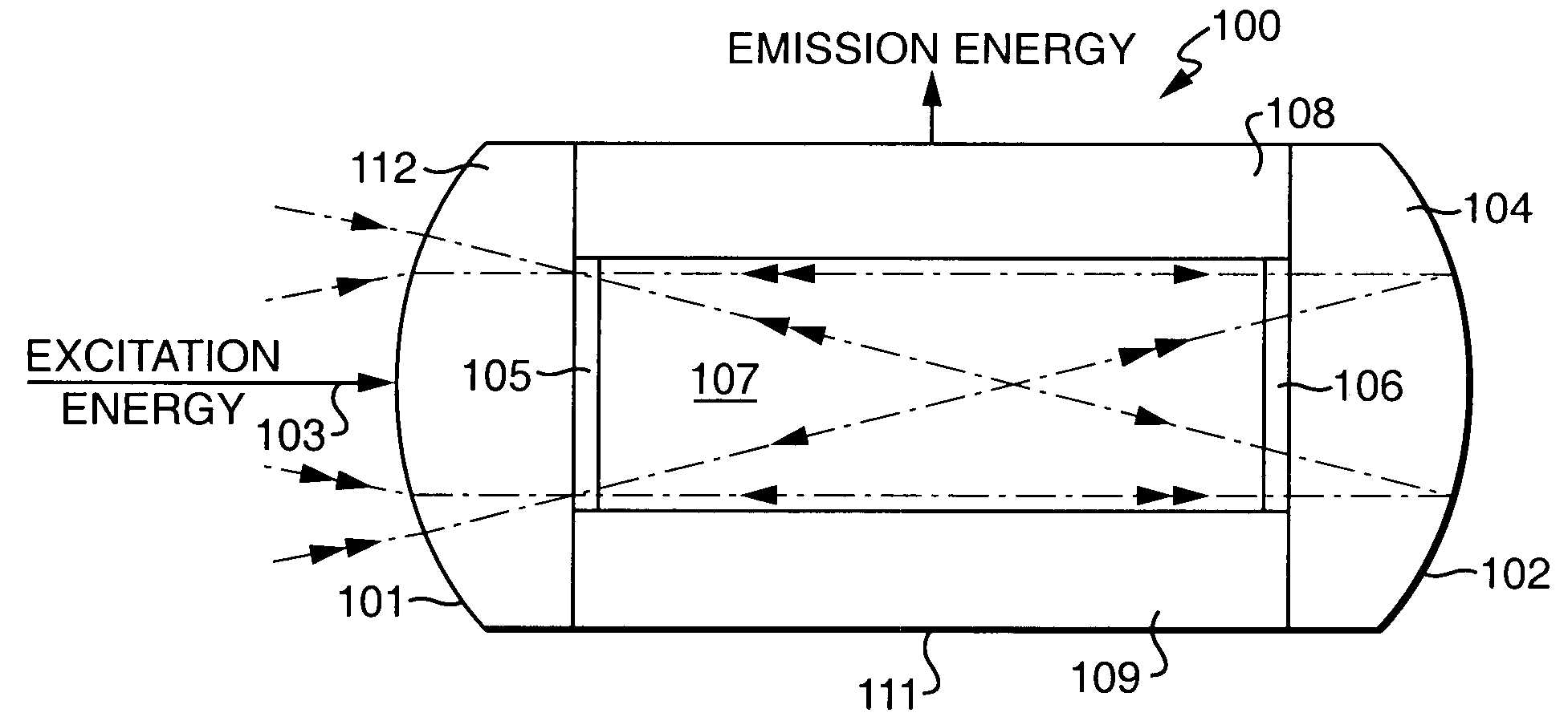
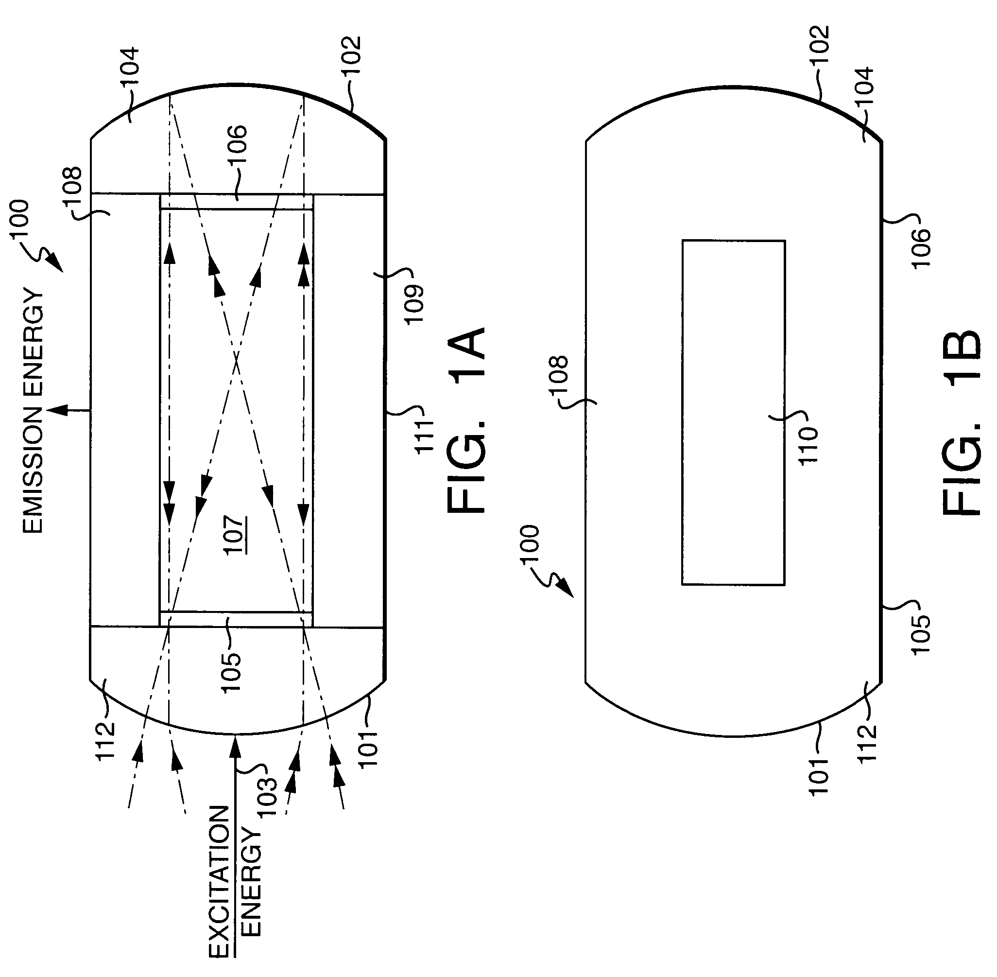
[0023]The flow cell according to the invention is used for analyzing small sample volumes typically between 0.5 to 15 μL. Generally, the analysis of these small sample volumes is accomplished with the use of an axially excited flow cell having a retro-reflective mirror that allows for an increased pathlength through the sample. The use of this inventive flow cell with excitation optics and emission optics on different planes allows for a significantly greater pathlength through a sample of interest and therefore greater sensitivity in the detector results.

[0024]Referring to FIGS. 1A and 1B, the flow cell 100 according to the invention is constructed from a combination of black quartz and clear non-fluorescence quartz. The clear quartz is UV grade having a low fluorescence, such as Suprasil or an equivalent clear quartz known to those skilled in the art. The flow cell 100 has a proximal end 101 and a distal end 102. The proximal end 101 contains an excitation lens 112 that allows an ...


PUM

PropertyMeasurementUnit
volumeaaaaaaaaaa
volumeaaaaaaaaaa
volumeaaaaaaaaaa

Abstract

Excitation light of a selected wavelength from an excitation monochromator is directed along the long axis of a flow cell containing the sample to be analyzed, generating fluorescence. An emission monochromator is positioned at right angles to the plane of the excitation monochromator and receives the fluorescence from the flow cell utilizing optical components positioned such that the entrance slit of the emission monochromator is aligned with the long axis of the emission window. The intensity of the output from the flow cell is further maximized by positioning a retro-reflecting mirror at the end of the flow channel to effectively double the path-length of the excitation beam, and a reflecting surface on the side of the cell opposite the emission window to increase the collection efficiency and thereby increase the sensitivity of the detector.

Description

CROSS REFERENCE TO RELATED APPLICATIONS[0001]This application is a continuation of and claims priority from PCT Application PCT / US02 / 06336 filed Mar. 1, 2002, which designated the U.S. and claimed priority from U.S. Provisional Application 60 / 273,093, filed Mar. 2, 2001. The contents of these applications are incorporated herein by reference.FIELD OF THE INVENTION[0002]The present invention relates to fluorescence detectors, and more particularly to an axially illuminated flow cell having a significantly greater excitation path length per unit volume allowing for improved sensitivity.BACKGROUND OF THE INVENTION[0003]In the measurement of fluorescence and exitation spectra it is customary to illuminate a sample with monochromatic light from an intense source and to observe the fluorescence emitted by the sample with a monochromator and a photoelectric detection system.[0004]Conventional fluorescence detectors are based on monochromators and an incoherent light source that have essent...

Claims


Application Information

Patent Timeline
Patent Type & Authority Patents(United States)
IPC IPC(8): G01N1/10G01N21/03G01N21/05G01N21/64
CPCG01J3/02G01J3/0208G01J3/18G01J3/4406G01N21/0303G01N21/031G01N21/05G01N21/645G01N30/74G01N2021/0314G01N2021/6482G01N2021/0346
Inventor GILBY, ANTHONY C.
Owner WATERS TECH CORP
Why Eureka
Try Eureka