Optical pickup that uses light sources with different wavelengths for each of multiple recording mediums

a technology of optical pickup and recording medium, which is applied in the direction of optical beam sources, data recording, instruments, etc., can solve the problems of affecting the compatibility with different kinds of optical disks, and affecting the focusing characteristic of the aperture spot, so as to prevent the focusing characteristic from being severely impaired, the effect of suppressing the displacement of the focal poin

Inactive Publication Date: 2007-08-21
SHARP KK
View PDF13 Cites 28 Cited by
  • Summary
  • Abstract
  • Description
  • Claims
  • Application Information

AI Technical Summary

Benefits of technology

[0027]An object of the present invention is to provide an optical pickup that can (a) record or reproduce information with respect to recording media respectively having light transmissive layers of different thicknesses and respectively using optimum light beams of different wavelengths, (b) prevent light focusing characteristics from being severely impaired by radial shifting of an objective lens, and (c) suppress displacement of a focal point caused by wavelength fluctuations.

Problems solved by technology

However, a problem of increasing the NA of the objective lens is that it drastically increases the coma aberration that is caused when the optical disk tilts, with the result that the focusing characteristic of the aperture spot may be impaired.
However, this is faced with one problem; namely, compatibility with different kinds of optical disks is difficult to achieve when the wavelengths of light or thicknesses of the light transmissive layers are different between different kinds of optical disks.
Accordingly, in the event where the light transmissive layers of the optical disks have greatly different thicknesses or the optical disks use greatly different wavelengths, spherical aberration is caused on the aperture spot, impairing focusing characteristic of the aperture spot.
The objective lens cannot be used directly for the DVD or CD whose light transmissive layers have different thicknesses from that of the next-generation high-density optical disk, because in this case spherical aberration increases to the level where recording or reproducing cannot be carried out.
Here, the red light and infrared light, with their large degrees of divergence of incident ray on the objective lens, greatly impair the focusing characteristic of the light by causing coma aberration on the aperture spot on the optical disk when the objective lens shifts in the radial direction (direction substantially orthogonal to the optical axis of the incident light on the objective lens) during tracking or other operations.
With the objective lens having the diffracting face as disclosed in Publication 1, attaining diffraction efficiency of 100% for the first order component of one wavelength limits the diffraction efficiency for the first order component of the diffracted light of the other wavelengths, with the result that a desired level of high diffraction efficiency cannot be obtained.
This brings about the problem of poor light efficiency by a loss of light quantity.
Further, the diffracted rays of unnecessary orders may enter the detector as stray light when reproducing information, with the result that the signal may be impaired.
The strong wavelength dependency of the objective lens poses a problem in that a focal point deviates greatly in the presence of wavelength fluctuations caused by mode hopping or high-frequency superimposition, which cannot be followed by an actuator.
However, given the fact that the effective radius of the objective lens is 2 mm, and that the effective diameter of the diffraction optical element is also 2 mm, the refracting face with a curvature radius of no greater than 2.2 mm is substantially hemispherical, which is impossible to fabricate or practically useless.
The refracting face may be made aspherical, but in this case the exceedingly small curvature makes fabrication of the diffraction optical element difficult.
In this case, the optical pickup is unable to produce sufficient light quantity for the recording or reproducing of information with respect to CD.

Method used


Image

  • Optical pickup that uses light sources with different wavelengths for each of multiple recording mediums
  • Optical pickup that uses light sources with different wavelengths for each of multiple recording mediums
  • Optical pickup that uses light sources with different wavelengths for each of multiple recording mediums

Examples


first embodiment

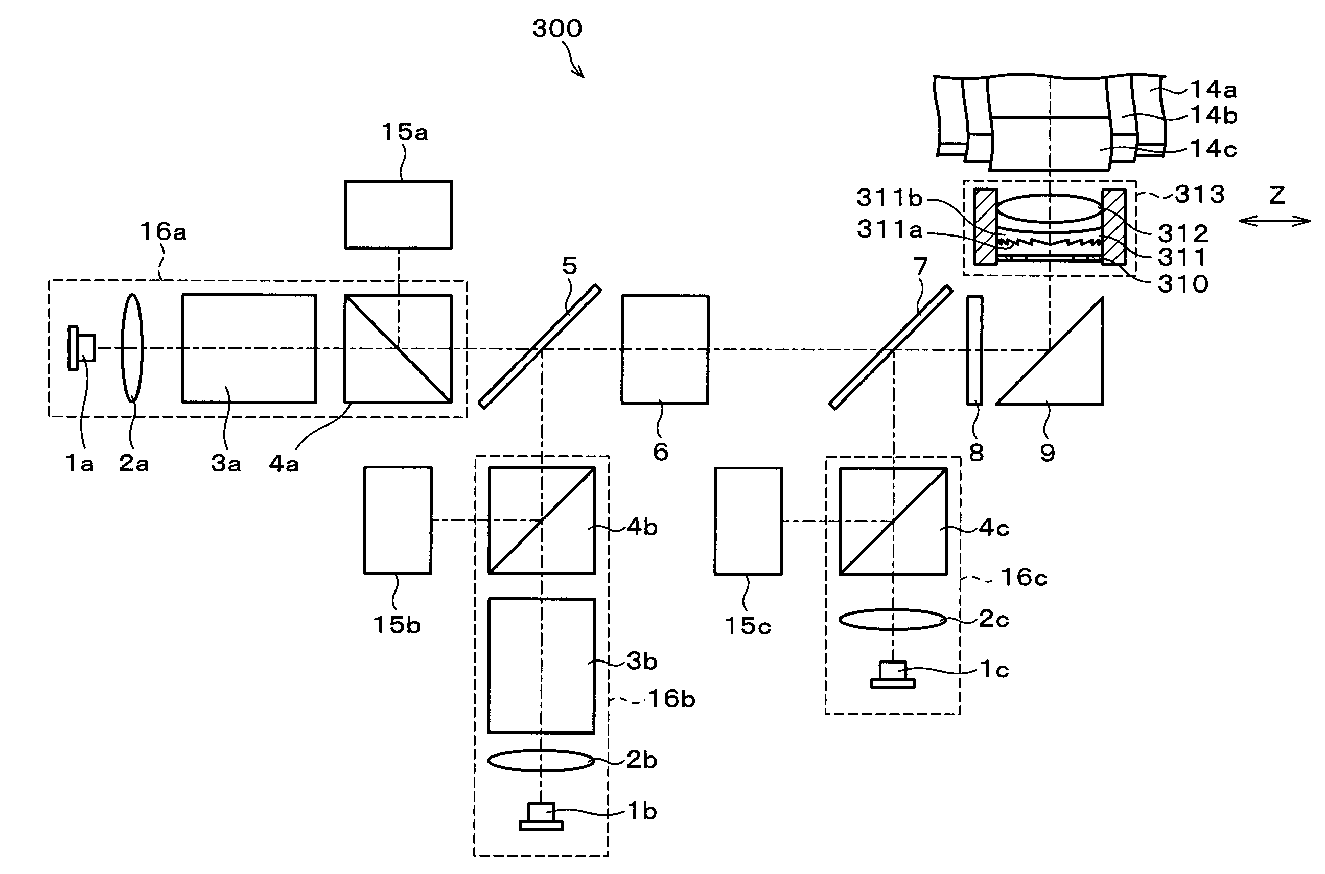
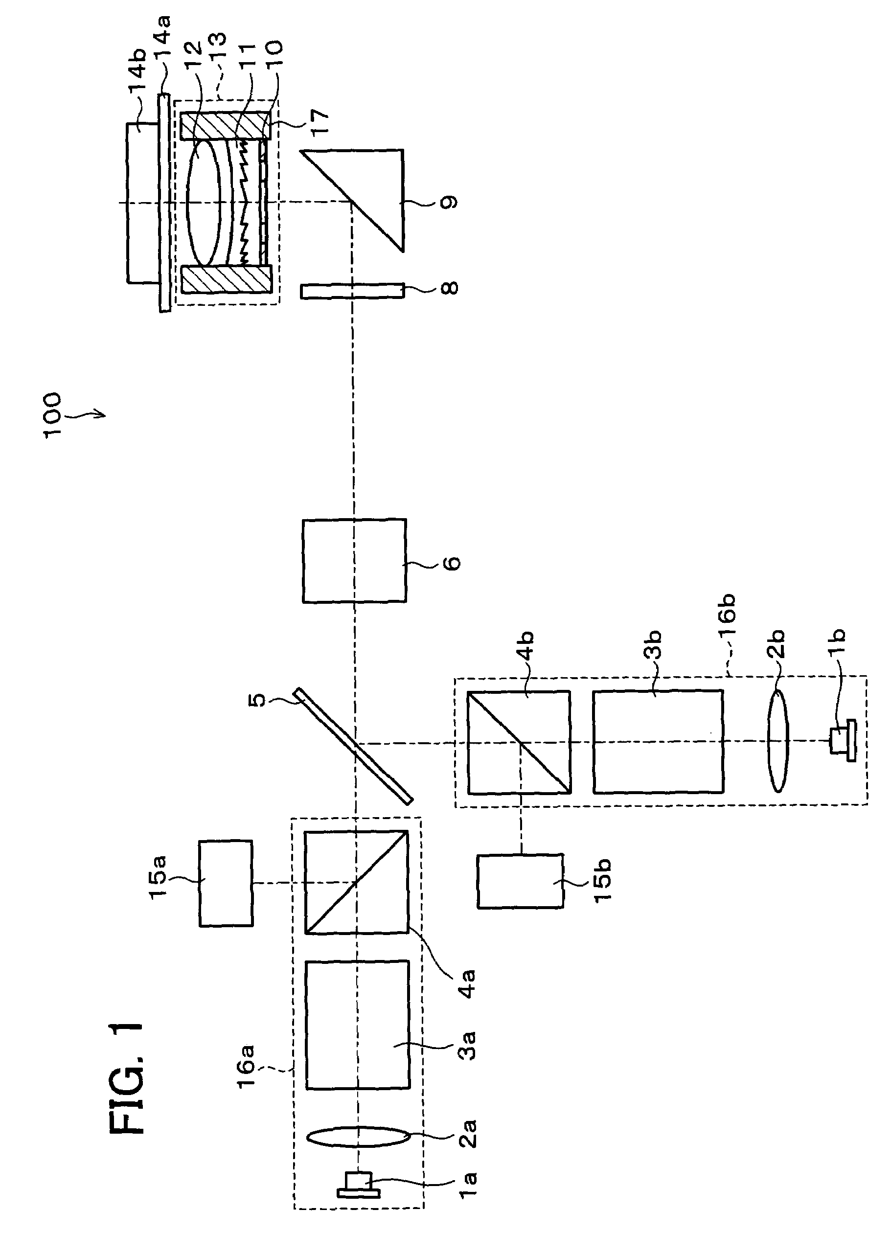
[0103]FIG. 1 illustrates a schematic structure of an optical pickup 100 of the present embodiment. The description of the present embodiment will be given based on the optical pickup 1 that is compatible with a next-generation high-density optical disk 14a (first optical disk, first recording medium) and a conventional DVD 14b (second optical disk, second recording medium).

[0104]The first optical disk uses blue light (first light beam) of a short wavelength in the vicinity of 405 nm (first wavelength λ1 ), and has a light transmissive layer with a thickness t1=0.1 mm. The second optical disk uses red light (second light beam) of a long wavelength in the vicinity of 650 nm (second wavelength λ2), and has a light transmissive layer with a thickness t2=0.6 mm.

[0105]The optical pickup 100 includes a semiconductor laser 1a that emits a first light beam 1 of the first wavelength λ1, and a semiconductor laser 1b that emits a second light beam 2 of the second wavelength λ2 longer than λ1. T...

example 1

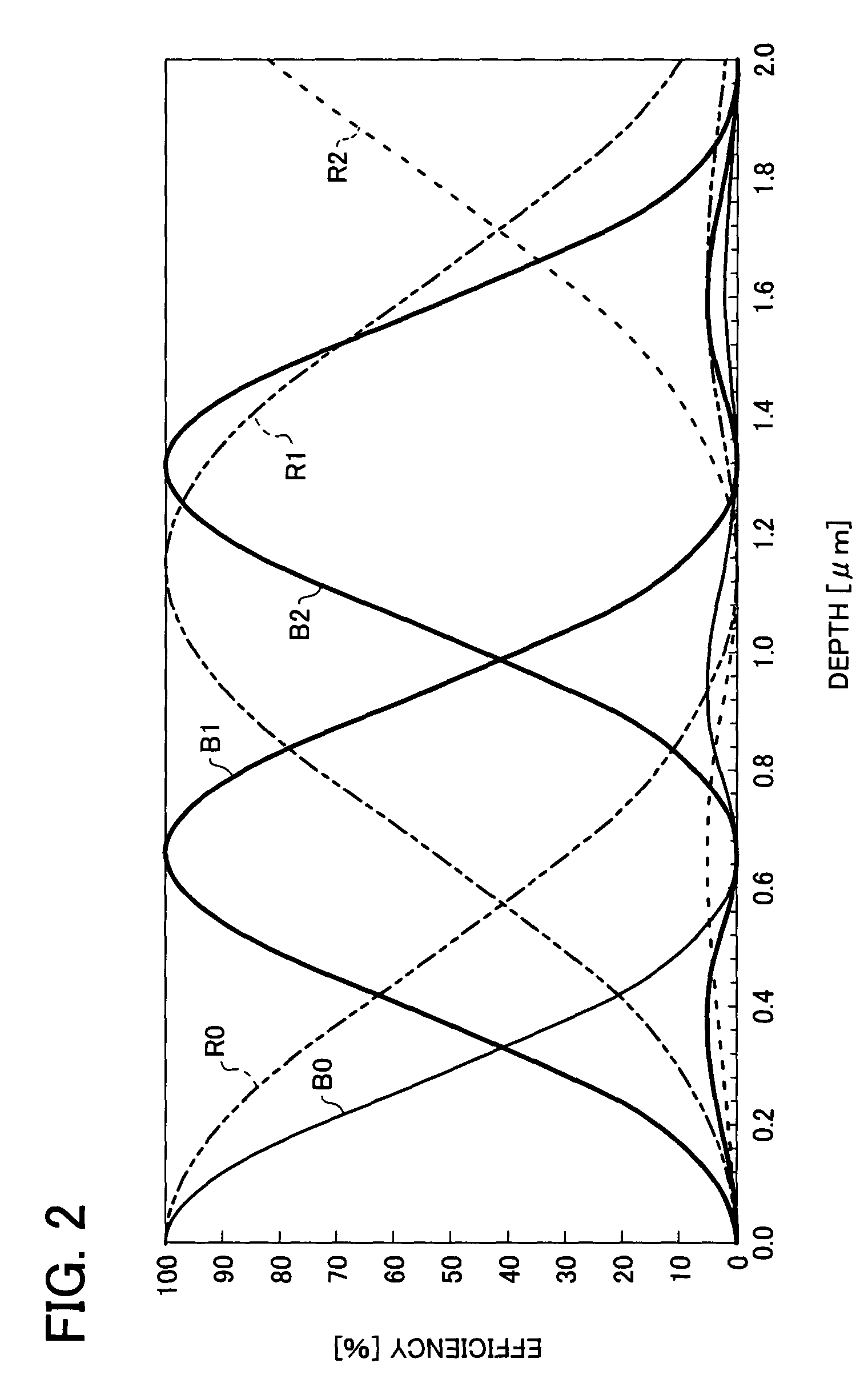
[0133]In this Example, the optical pickup 100 described in the foregoing First Embodiment includes a diffraction optical element 11 which is realized by a lens 116 that contains a diffraction grating 11a and a convex face 11c, as shown in FIG. 6(a) and FIG. 6(b), the diffraction grating 11a being disposed on the side of a light source. It is assumed in the following description that the base material (lens) of the diffraction optical element 11 is polycarbonate (PC), and the diffracted rays of the first light beam (λ=405 nm) and the second light beam (λ=650 nm) used are of the first order.

[0134]As shown in FIG. 6(a), a parallel ray of the laser beam (first light beam) of 405 nm wavelength incident on the diffraction optical element 11 diffracts on the face of the diffraction grating 11a in a direction of the first order diffraction (diverging direction). The first light beam then refracts as it passes through the convex face 11c and emerges from the diffraction optical element 11c a...

example 2

[0148]In this Example, the optical pickup 100 described in the foregoing First Embodiment includes, as shown in FIG. 7(a) and FIG. 7(b), an objective lens unit 113, instead of the objective lens unit 13 of the foregoing Example 1. That is, the optical pickup includes a diffraction optical element 111 which is realized by a lens 111b made with a concave face 111c and a diffraction grating 111a, the diffraction grating 111a being disposed on the side of a light source. The base material (lens) of the diffraction optical element 111 is polycarbonate (PC), and the face of the diffraction grating 111a of the diffraction optical element 111 satisfies Equation (11) below.

[0149]sin-1⁡(m1⁢λ1d)-sin-1⁡(m2⁢λ2d)>0,(11)

where m1 is the diffraction order of the first diffracted light, m2 is the diffraction order of the second diffracted light, and d is the groove separation of the diffraction grating. It is assumed in the following description that the diffraction order m1 of the first diffracte...


PUM

PropertyMeasurementUnit
thicknessaaaaaaaaaa
thicknessaaaaaaaaaa
wavelengthsaaaaaaaaaa

Abstract

An optical pickup includes: a first projector for projecting a first light beam of a first wavelength so as to record and reproduce information with respect to an optical disk having a first light transmissive layer; a second projector for projecting a second light beam of a second wavelength longer than the first wavelength so as to record and reproduce information with respect to an optical disk having a second light transmissive layer; an objective lens common to the first and second light beams; and a diffraction optical element made of a lens with a diffraction grating and a refracting face and disposed in an optical path between the first and second projectors and the objective lens. The diffraction optical element is set to satisfy a predetermined equation. As a result, an optical pickup is realized that uses a single focusing means to focus light beams of different wavelengths, so as to record and reproduce information with respect to different kinds of optical disks (recording media) respectively having light transmissive layers of different thicknesses and respectively using different optimum wavelengths of light for reproducing.

Description

FIELD OF THE INVENTION[0001]The present invention relates to an optical pickup for recording and reproducing information with respect to a recording medium, and particularly to an optical pickup for recording and reproducing information with respect to different types of recording media whose light transmissive layers, from a light incident face to an information recording face, have different thicknesses, and whose optimum light beam wavelengths are different.BACKGROUND OF THE INVENTION[0002]Conventionally available are optical disk players (optical recording and reproducing apparatus) that can read recorded information from optical disks (optical recording medium), for example, such as DVD (Digital Video Disc) and CD (Compact Disc). DVDs currently available in the market have the capacity as high as 4.7 GB, yet demand for higher density optical disks has been strong and there has been ongoing study for realizing such optical disks. It is well known that recording density can be ef...

Claims


Application Information

Patent Timeline
Patent Type & Authority Patents(United States)
IPC IPC(8): G11B7/00G11B7/125G11B7/135
CPCG02B27/42G11B7/1275G11B7/1353G11B7/1378G11B7/139G11B7/13925G11B2007/0006
Inventor NISHIOKA, SUMITOOGATA, NOBUONAKANO, IKUO
Owner SHARP KK
Why Eureka
Try Eureka