
Programmable pattern generation for dynamic bus signal integrity analysis

Inactive Publication Date: 2007-09-04
GLOBALFOUNDRIES INC
View PDF6 Cites 6 Cited by
  • Summary
  • Abstract
  • Description
  • Claims
  • Application Information

AI Technical Summary

Benefits of technology

[0018]In another embodiment, the system includes con

Problems solved by technology

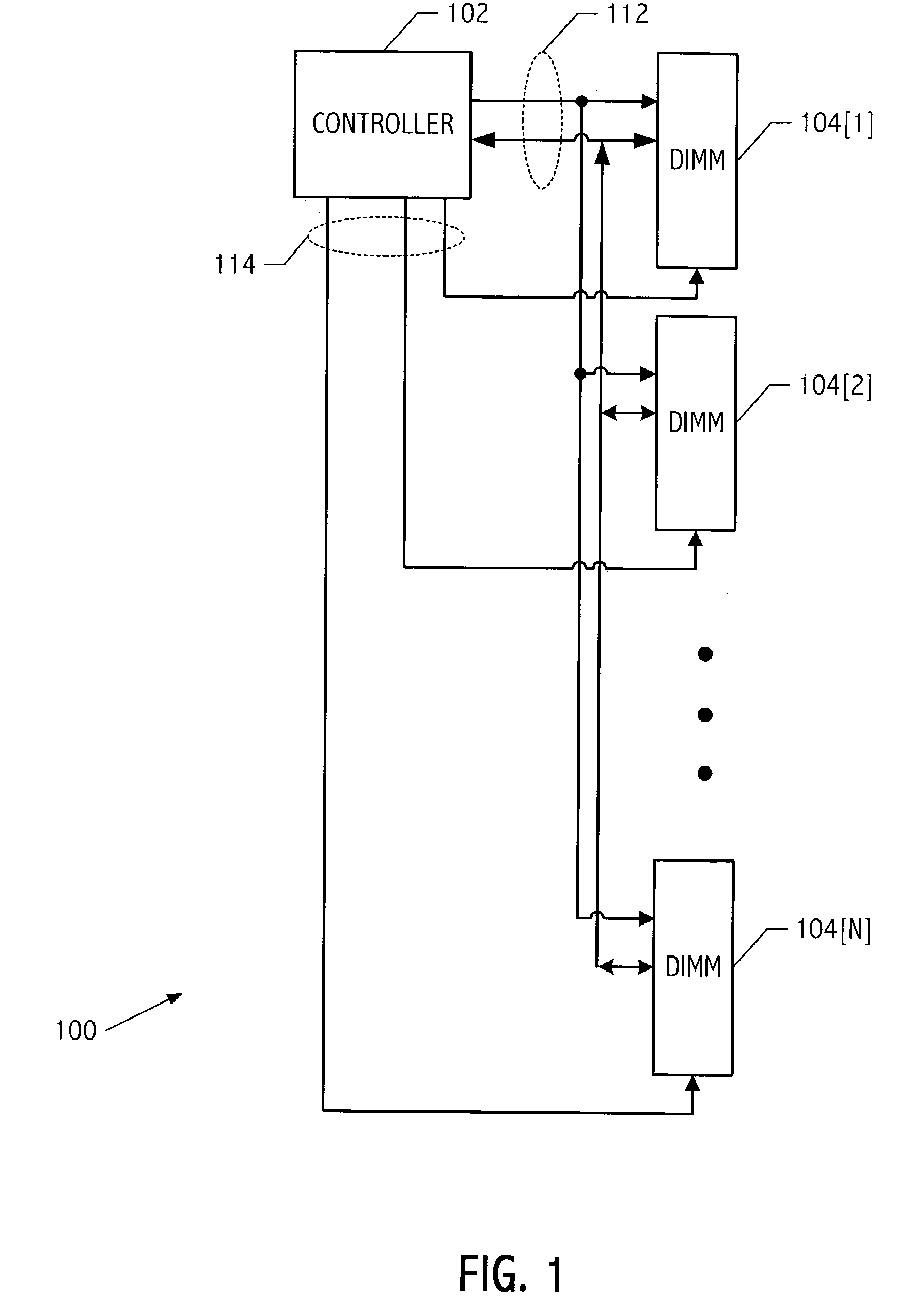
Simulation of an electronic system, for example, a having large amounts of signal traces connecting multiple integrated circuit devices (ICs), is a complicated and time consuming process.
At high-speeds PCB traces, as well as connectors and IC packages, can make up a significant part of the overall signal delay.
Even worse, interaction between signal traces can cause glitches, resets, logic errors, and other problems.
Crosstalk between signals increases proportionally to the clock rate and can cause data dependent logic errors.
Ground bounce and power supply noise increases with higher-powered drivers, increased switching rates, and parallel bus structures.
However, terminators occupy precious space on PCBs, and dissipate large amounts of power.
However, digital simulators do not support analysis of analog characteristics such as transmission line effects and the interaction between PCB traces in a system.
Analog simulators such as HSPICE can provide some analog analysis of signals, but provide results only as good as the input stimulus and noise model.
Design cycles are short and the vast number of possible interactions between signal traces has typically made signal integrity analysis too expensive in time and labor to complete thoroughly.
Signal integrity noise analysis performed with signal patterns that do not occur in the bus protocol run the risk of over-estimating signal integrity problems the system will experience in actual operation.

Method used


Image

  • Programmable pattern generation for dynamic bus signal integrity analysis
  • Programmable pattern generation for dynamic bus signal integrity analysis
  • Programmable pattern generation for dynamic bus signal integrity analysis

Examples


Embodiment Construction

)

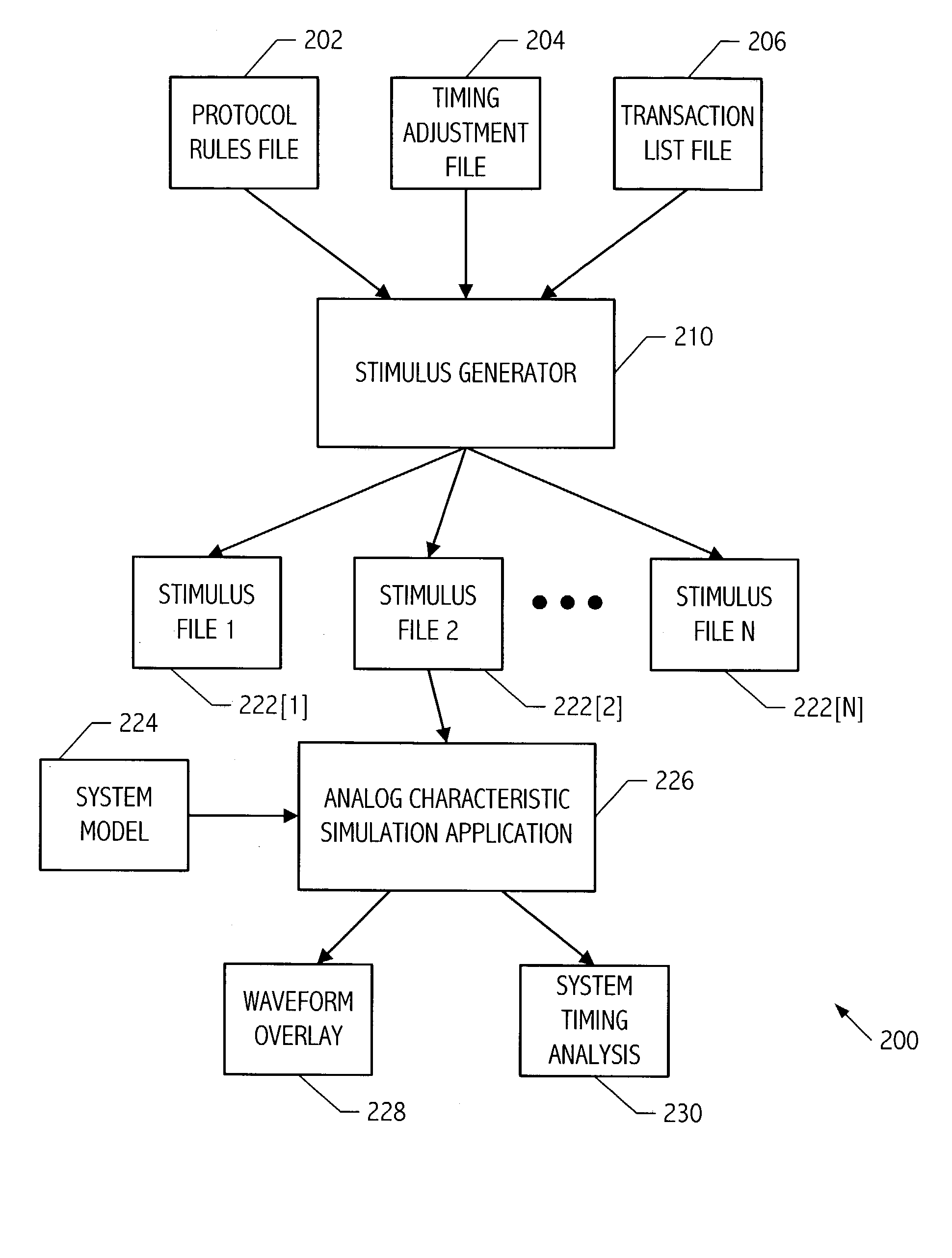
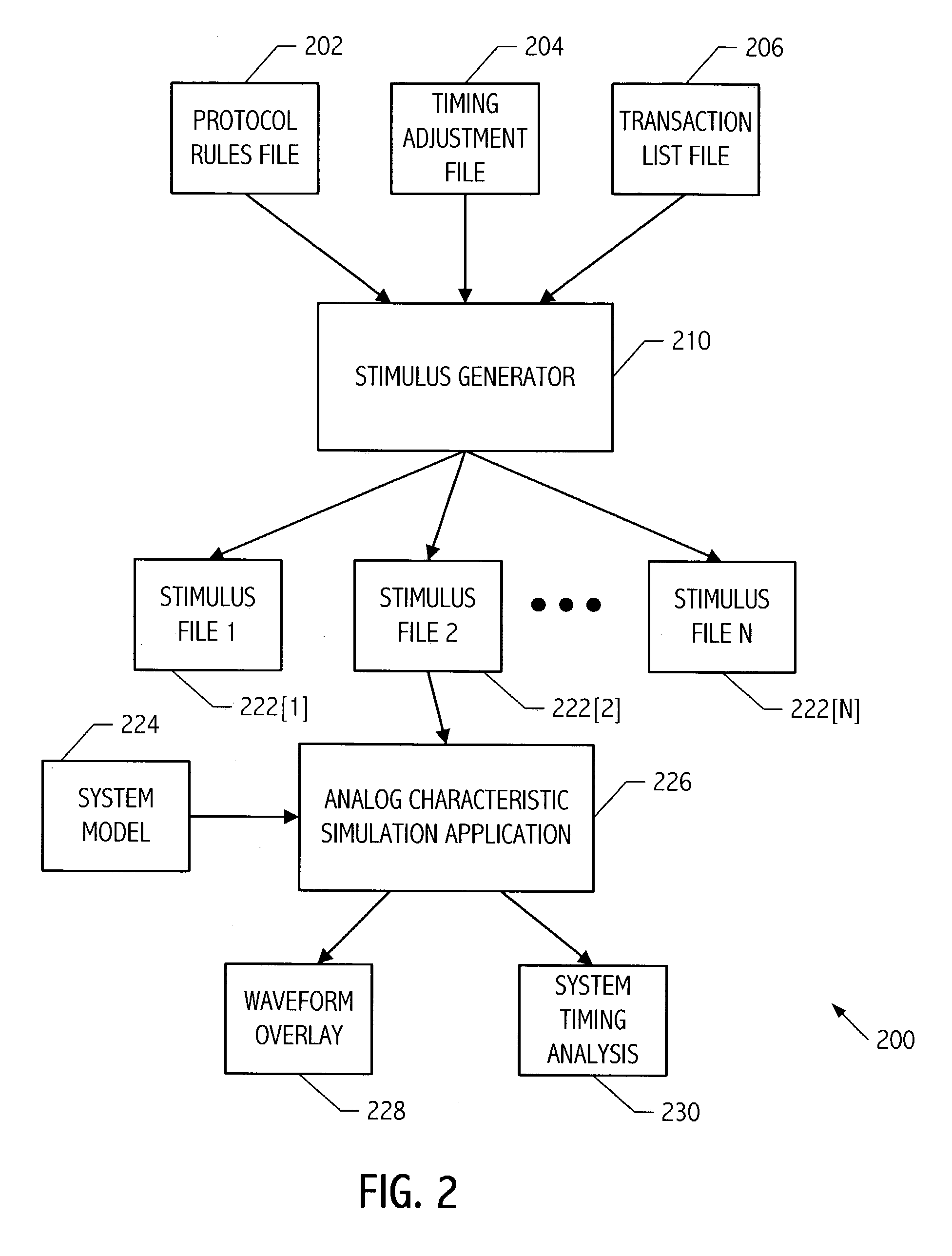
[0028]An automated software process to produce complex signaling scenarios for signal traces in a system is presented. The complex signaling scenarios include sequences of signal transitions according to bus protocols and system characteristics that can be used to perform signal integrity analysis. By producing complex signaling scenarios in a stimulus file, signal integrity analysis can be performed efficiently and comprehensively, allowing the design process to produce a more reliable and efficient system design. The ability to modify one or more input parameters, for example, a change in timing of the bus protocol, a desired pattern type, a signal timing adjustment, system configuration, and the like, is greatly simplified, thereby improving analysis time significantly. Signal integrity analysis can be used to improve PC board layout, determine necessary protocol timing, determine output driver strengths, determine necessary termination and timing for PCB traces, and the like.

[0...


PUM


Abstract

A technique for performing signal integrity analysis of a system includes providing a stimulus pattern and a model of the system and performing analog simulation of the model utilizing the stimulus pattern. The stimulus pattern includes sequences of signal transitions with associated transition times and the sequences of signal transitions conform to a bus protocol and the associated transition times are according to characteristics of the system. The stimulus pattern is generated by initializing each of the sequences of signal transitions to an initial signal value and the associated transition times to an initial time, generating subsequent signal values and subsequent transition times by applying protocol rules and calculating timing adjustments for each of a list of transactions; the subsequent signal values and subsequent transition times to be added to the sequences of signal transitions.

Description

COMPUTER PROGRAM LISTING APPENDIX[0001]Submitted with the application and incorporated by reference are two computer program listings stored on each of two duplicate compact disks (labeled COPY 1 and COPY 2). Each disk contains computer program listings in the C++ programming language which illustrate implementations of the invention. The listings are recorded as ASCII text in IBM PC / MS DOS compatible files which have the names, sizes (in kilo bytes) and creation dates listed below: ddrstimulator_header_functions.txt 4149 bytes (5 kb) Feb. 5, 2003 ddrstimulatorcode.txt 41,944 bytes (41 kb) Feb. 5, 2003COPYRIGHT NOTICE[0002]A portion of the disclosure of this patent document, including certain figures and the Computer Program Listing Appendix, contains material that is subject to copyright protection. The copyright owner has no objection to the facsimile reproduction by anyone of the patent document or the patent disclosure as it appears in the Patent and Trademark Office patent file...

Claims


Application Information

Patent Timeline
IPC IPC(8): G06F17/50G06F7/48G06F7/60G06F9/45
CPCG06F17/5022G06F30/33
Inventor WALLACE, JR., DOUGLAS E.DOWLING, JONATHAN P.
Owner GLOBALFOUNDRIES INC
Learn More