

Process for the producing of electrolytic capacitors
a technology of electrolytic capacitors and electrolytic capacitors, which is applied in the direction of electrolytic capacitors, capacitor electrodes, liquid electrolytic capacitors, etc., can solve the problems of increasing the leakage current of the capacitor anode, destroying the conductivity of the outer layer at the defect site, and insufficient stability of the film produced by the film on the outer anode surface with respect to external stresses
- Summary
- Abstract
- Description
- Claims
- Application Information
AI Technical Summary
Benefits of technology
Problems solved by technology
Method used
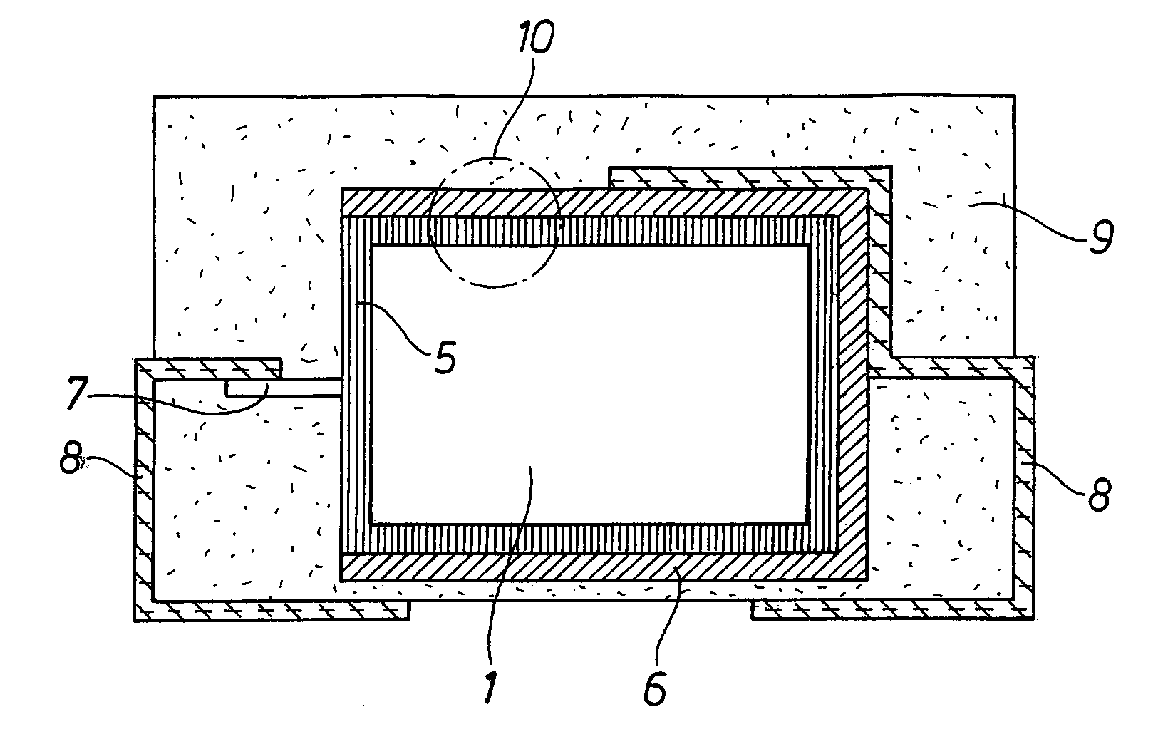
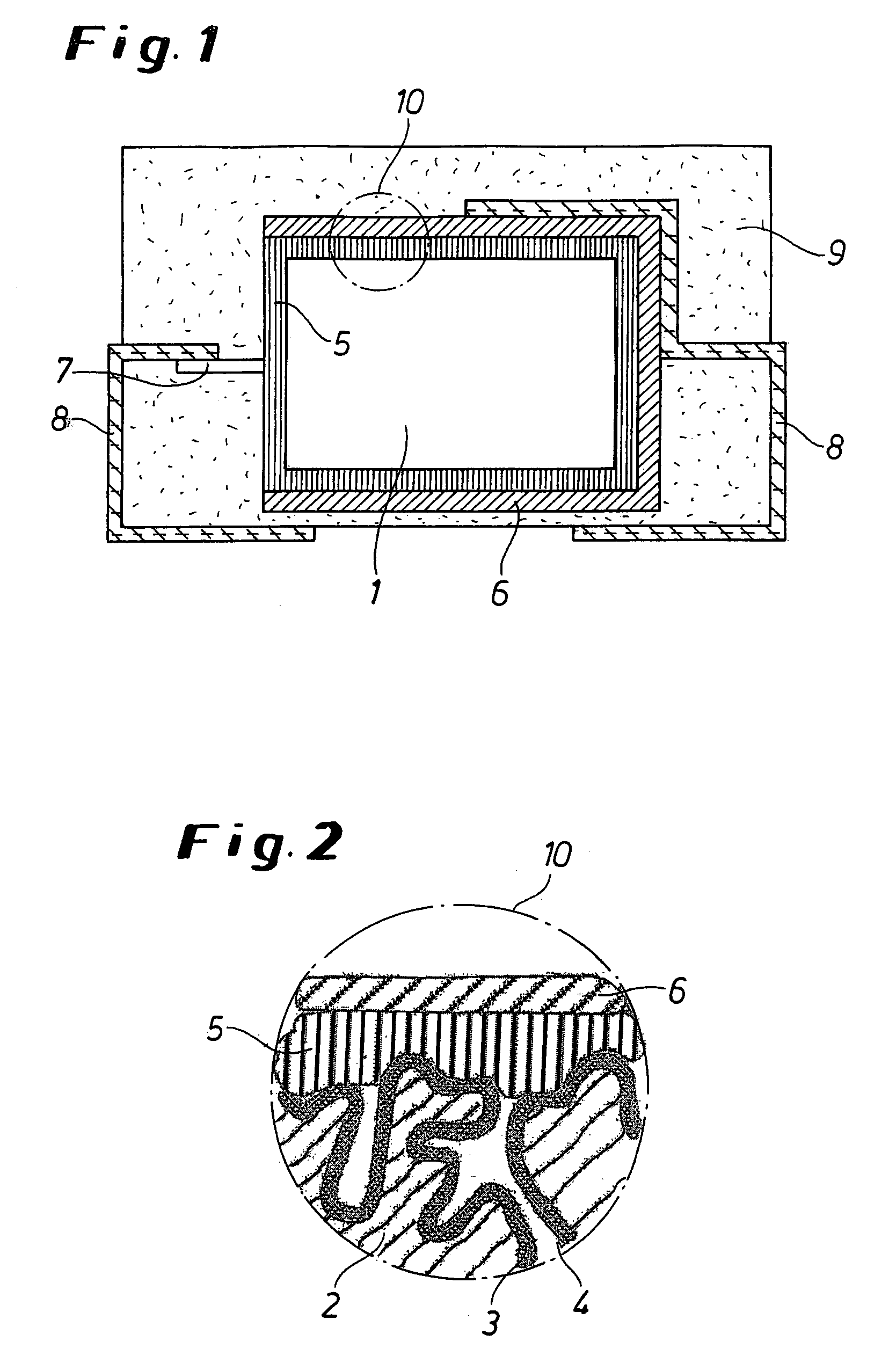
Image

Examples
example 1
1. Production of Oxidized Electrode Bodies
[0176]Tantalum powder having a specific capacitance of 50,000 μFV / g was compressed into pellets and sintered in order to form a porous electrode body of dimension 4.2 m×3 mm×1.6 mm. The pellets (anode pellets) were anodized at 30 V in a phosphoric acid electrolyte.
2. Chemical in situ Coating According to the Invention of the Anode Pellets
[0177]A solution was prepared consisting of 1 part by weight of 3,4-ethylenedioxythiophene (BAYTRON® M, H.C. Starck GmbH) and 20 parts by weight of a 40 wt. % ethanolic solution of iron(III) p-toluenesulfonate (BAYTRON® C-E,H. C. Starck GmbH).
[0178]The solution was used to impregnate the anode pellets. The anode pellets were immersed in this solution and then exposed for 30 minutes at room temperature (20° C.) to an atmospheric relative humidity of 95%. Following this they were heat treated for 15 minutes at 50° C. and for 15 minutes at 150° C. in a drying cabinet. The pellets were then washed for 30 minutes...
example 2
Production of Capacitors According to the Invention
1. Production of Oxidized Electrode Bodies
[0182]Tantalum powder having a specific capacitance of 50,000 μFV / g was compressed into pellets and sintered in order to form a porous electrode body of dimension 4.2 mm×3 mm×1.6 mm. The pellets (anode pellets) were anodized at 30 V in a phosphoric acid electrolyte.
2. Chemical in situ Coating of the Anode Pellets
[0183]A solution was prepared consisting of 1 part by weight of 3,4-ethylenedioxythiophene (BAYTRON® M, H.C. Starck GmbH) and 20 parts by weight of a 40 wt. % ethanolic solution of iron(III) p-toluenesulfonate (BAYTRON® C-E, H.C. Starck GmbH).
[0184]The solution was used to impregnate 7 anode pellets. The anode pellets were immersed in this solution and then exposed for 30 minutes at room temperature (20° C.) to a relative atmospheric humidity of 95%. Following this they were heat treated for 15 minutes at 50° C. and for 15 minutes at 150° C. in a drying cabinet. The pellets were then...
example 3.1
Production of Capacitors According to the Invention
[0193]7 capacitors were fabricated similarly to Example 2, except that the anode pellets after the impregnation and the 15-minute exposure to an atmospheric relative humidity of 95% at 20° C. were then heat treated for 30 minutes at 50° C.
PUM
| Property | Measurement | Unit |
|---|---|---|
| temperature | aaaaa | aaaaa |
| temperature | aaaaa | aaaaa |
| atmospheric humidity | aaaaa | aaaaa |
Abstract
Description
Claims
Application Information