Rapid thermal processing lamp and method for manufacturing the same

a technology of thermal processing lamp and substrate, which is applied in the direction of muffler furnace, furnace, instrument, etc., can solve the problems of under-heating, uncontrollable characteristics of the layer, and the life of known rtp heaters, and achieve the effect of fast processing

Inactive Publication Date: 2007-10-23
TOKYO ELECTRON LTD
View PDF14 Cites 10 Cited by
  • Summary
  • Abstract
  • Description
  • Claims
  • Application Information

AI Technical Summary

Benefits of technology

[0014]It is a further object of the present invention to integrate the lamp into an upper injection plate for fa...

Problems solved by technology

Overheating can cause dopants to permeate subjacent layers, and under-heating can produce layers with uncontrolled characteristics.
Known RTP heaters have a relatively short lifetime because those lamps have a physical connection between their filaments and their power supplies...

Method used


Image

  • Rapid thermal processing lamp and method for manufacturing the same
  • Rapid thermal processing lamp and method for manufacturing the same
  • Rapid thermal processing lamp and method for manufacturing the same

Examples


first embodiment

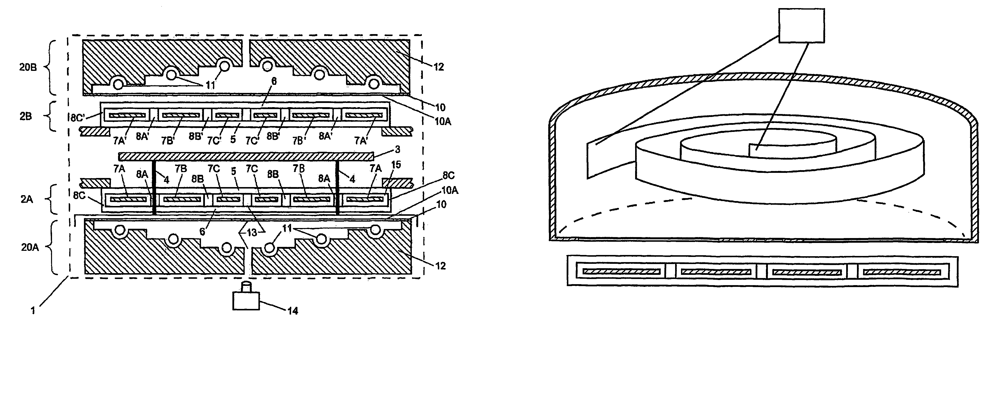
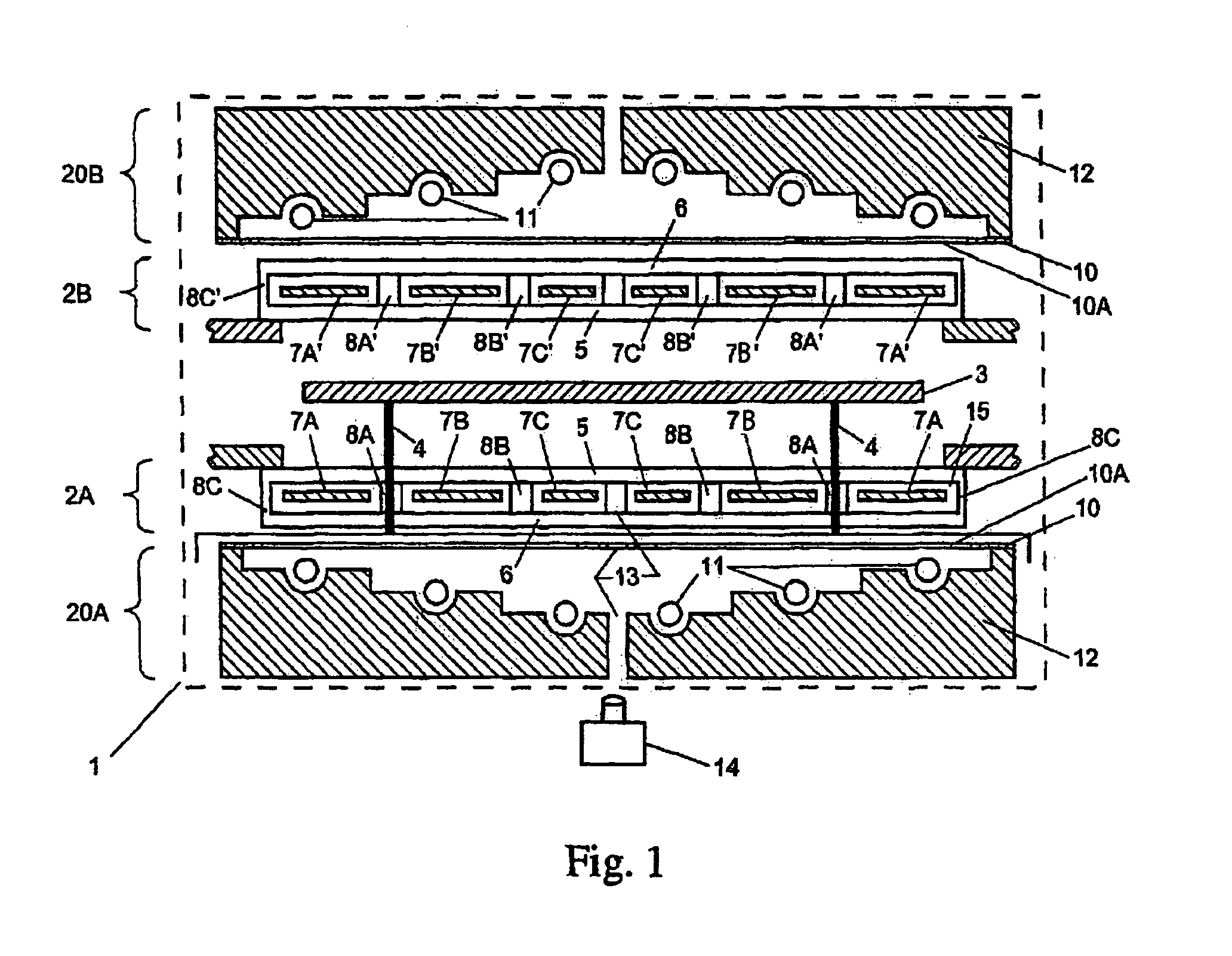
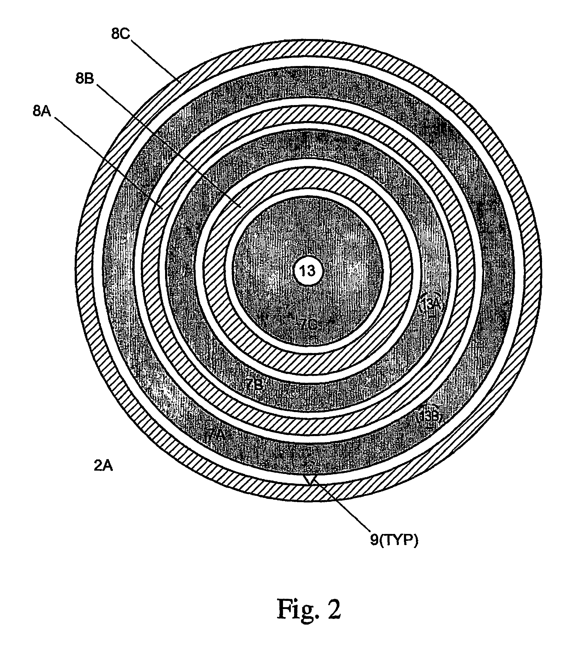
[0021]Referring now to the drawings, wherein like reference numerals designate identical or corresponding parts throughout the several views, FIG. 1 illustrates the present invention. The apparatus includes a chamber 1 to which heated lamp assemblies 2a and 2b (e.g., RF induction heated lamp assemblies) are fitted. A substrate 3 (e.g., a silicon wafer or LCD panel) to be heat-treated is located substantially midway between the two lamp assemblies (2a and 2b) on pins 4 (e.g., quartz pins). (As would be apparent to one skilled in the art, the present invention may selectively and alternately illuminate (1) the top side, (2) the bottom side or (3) both sides of the substrate 3.) Alternately, a single lamp assembly can be used. The lamp assemblies 2a and 2b include a first isolation plate 5, a second isolation plate 6, and at least one of (1) filament rings 7a, 7b, 7c, 7a′, 7b′ and 7c′, (2) a ring of filament coils, (3) a wavy filament structure, or (4) a ring made of weaving wires. The...

second embodiment

[0023]A shield 10 (e.g., an RF-, a heat- or a combination RF / heat-shield) is fitted between the heated lamp assemblies (2a and 2b) and corresponding cooled induction coil assemblies 20a and 20b. The cooled RF induction coils 11 are mounted in a cooled structure 12 (e.g., a water- or air-cooled cup) (preferably made of a conductive material (e.g., OFHC copper, plated with gold)). In one embodiment, the shield 10 is made of a piece of metal plate (e.g., a gold plate) with a radial pattern of slots 10a therein. In a second embodiment, an isolation plate (e.g., a quartz plate) is coated with a metal (e.g., gold-plated on the side towards the lamp) and formed with a radial pattern of slots; hence comprising the shield 10. The (radially) slotted shield 10 serves two primary functions, namely, (1) the radial pattern of slots in the shield 10 will permit the RF field to penetrate so that it will inductively couple power with the tungsten rings 7, while (2) the RF / heat shield 10 will keep ex...


PUM


Abstract

A method and system for inductively coupling energy to a heating filament (7A′, 7B′, 7C′, 7A, 7B, 7C) in a thermal processing environment. By applying AC power to a coil antenna (11) and inductive coupling to a filament (e.g., a halogen lamp filament), a number of connections that are subject to fatigue is reduced, thereby increasing the reliability of the heater (2A, 2B). Such an environment can be used to process semiconductor wafers (3) and liquid crystal displays.

Description

CROSS-REFERENCE TO RELATED APPLICATIONS[0001]This application is a National Stage of International Application No. PCT / US01 / 44708 filed Dec. 12, 2001, which claims the benefit of U.S. Provisional Application No. 60 / 254,573 filed Dec. 12, 2000. The present invention is related to the following patent applications: “Multi-Zone Resistance Heater,” U.S. Provisional Ser. No. 60 / 156,595 filed Sep. 29, 1999; and, entitled “Multi-Zone Resistance Heater,” filed Sep. 18, 2000. The contents of all of those applications are incorporated herein by reference.BACKGROUND OF THE INVENTION[0002]1. Field of the Invention[0003]The present invention is directed to an apparatus for rapidly heating a substrate to be processed, and more particularly to an apparatus for heating during a rapid thermal processing of a semiconductor wafer or a liquid crystal display.[0004]2. Discussion of the Background[0005]Rapid Thermal Processing (RTP) and epitaxy in semiconductor chip manufacturing are processes where a he...

Claims


Application Information

Patent Timeline
IPC IPC(8): F27B5/14F27D11/06H05B11/00H05B6/02F27B17/00H01L21/00H05B3/00H05B6/10
CPCF27B17/0025H05B6/105H05B3/0047H01L21/67115
Inventor JOHNSON, WAYNE L.
Owner TOKYO ELECTRON LTD
Why Eureka
Try Eureka